Tensioner for the controlled clamping and moving of an elongated body, in particular for an installation for laying pipelines, umbilicals or cables

a technology of elongated body and tensioner, which is applied in the direction of web handling, pipe laying and repair, thin material handling, etc., can solve the problems of affecting the operation of the tensioner. the effect of optimizing the operation

Active Publication Date: 2015-04-30
REEL
View PDF3 Cites 2 Cited by
  • Summary
  • Abstract
  • Description
  • Claims
  • Application Information

AI Technical Summary

Benefits of technology

The patent describes a tensioner that uses special operating means to efficiently clamp and move a body. This tensioner is particularly secure because it has a steady or almost steady clamping force, even in cases where the power supply is cut off.

Problems solved by technology

But the cables, umbilicals or pipelines frequently exhibit variations of section over their length, linked in particular to the presence of welding beads for assembling the various constitutive segments (causing diameter defects, generally of the order of 15 mm), or due to the repairing operations performed in case of degradation (in this case, the variations of diameter may reach 40 mm, due to the additional repairing layers added).
Due to these variations of section, the clamping force applied by the present tensioners may change during the guidance of the laying, and be sometimes too high or too low.
On the other hand, the clamped segments of the body is not always optimally centred within the tensioner, hence creating effort differences between the guiding boxes.
Moreover, a problem is also met with the present tensioners in case of power supply cut-off.
Indeed, in this context, the boxes are immobilized relative to each other, whereas the associated body is liable to still exert significant efforts on either one of said boxes.

Method used


Image

  • Tensioner for the controlled clamping and moving of an elongated body, in particular for an installation for laying pipelines, umbilicals or cables
  • Tensioner for the controlled clamping and moving of an elongated body, in particular for an installation for laying pipelines, umbilicals or cables
  • Tensioner for the controlled clamping and moving of an elongated body, in particular for an installation for laying pipelines, umbilicals or cables

Examples


Embodiment Construction

[0027]The invention will be further illustrated, without being limited in any way, by the following description of a particular embodiment, given only by way of example, and shown in the appended drawings, in which:

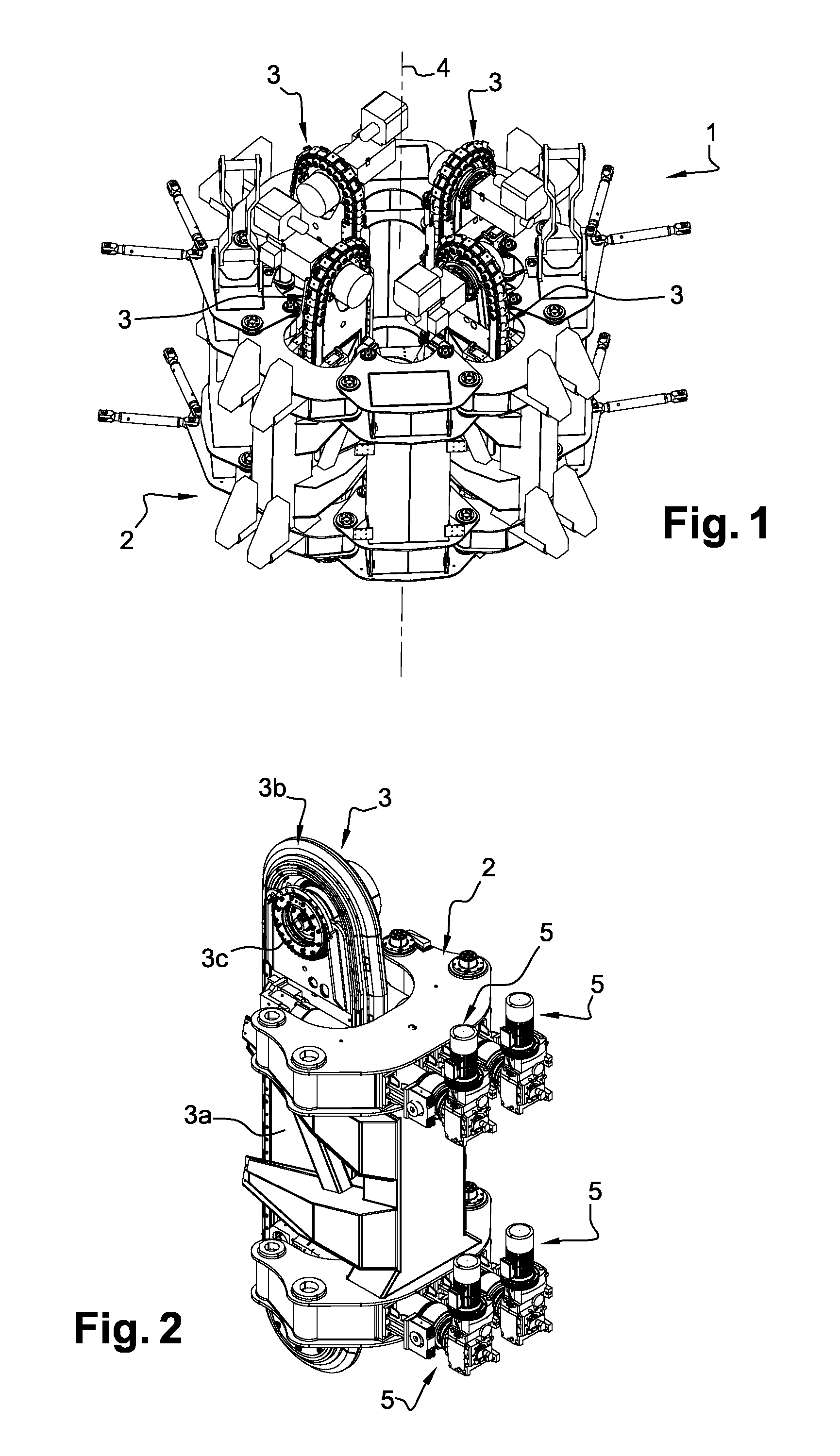
[0028]FIG. 1 is an overall perspective view of a tensioner according to the invention;

[0029]FIG. 2 is a perspective view of one of the guiding boxes equipping the tensioner of FIG. 1, and of its translation operating means;

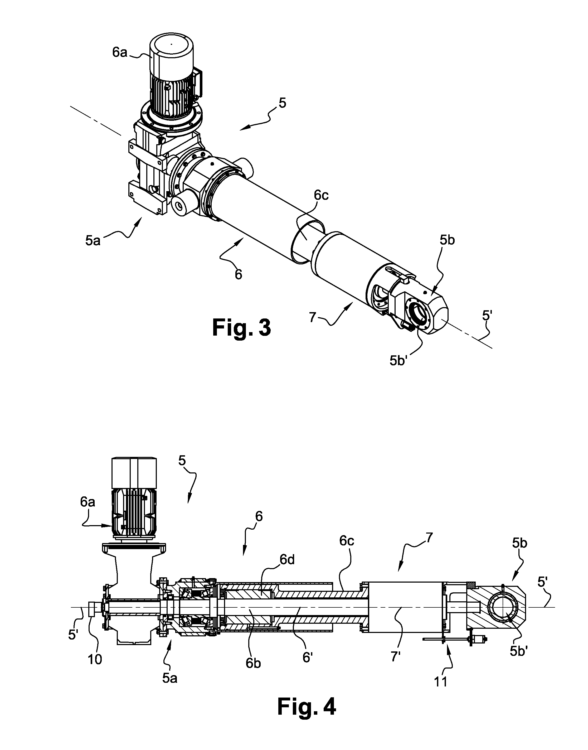
[0030]FIG. 3 is a perspective view of a linear actuator constitutive of the means for operating the boxes according to FIG. 1 or 2;

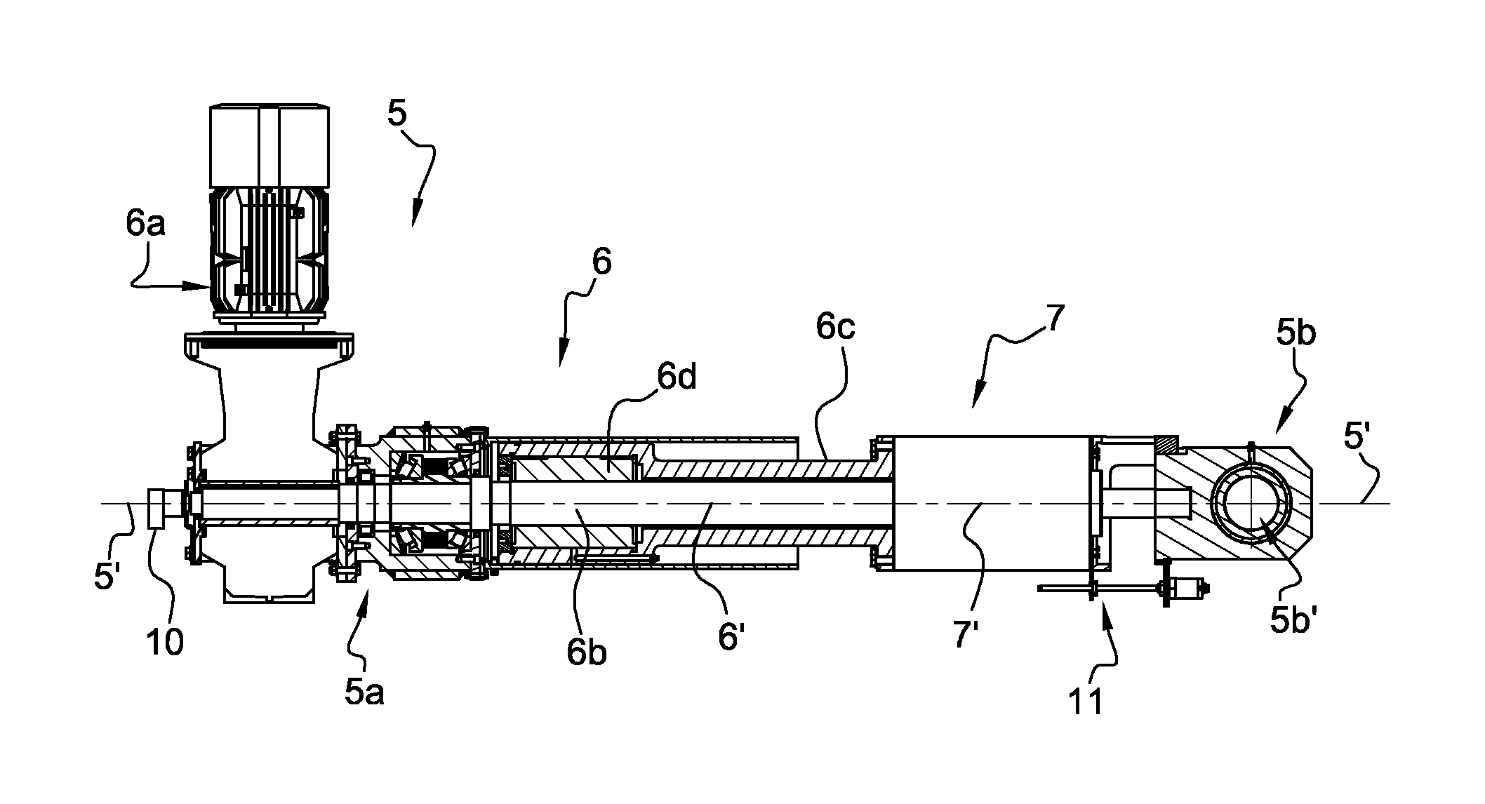
[0031]FIG. 4 is a side view of the linear actuator of FIG. 3, with a longitudinal sectional plane;

[0032]FIGS. 5A and 5B show the linear actuator according to FIGS. 3 and 4, in two different configurations: on the one hand, with the operating cylinder retracted and the elastic spring means deployed, in FIG. 5A (viewed from the side and according to a longitudinal sectional plane), and on the other hand, with the operating cyl...


PUM


Abstract

A tensioner for the controlled clamping and moving of an elongated body (A), in particular for an installation for laying pipelines, umbilicals or cables, includes a frame carrying at least two guiding boxes (3) that are arranged about an axis of symmetry (4), for clamping a segment of the elongated body (A). The guiding boxes (3) according to the invention are mounted mobile on their support frame through operating elements (5) including: (i) at least one linear actuator (5) including an operating cylinder extended by spring element, which operating cylinder and which spring element each have a longitudinal extension axis, the extension axes being oriented coaxially, or at least approximately coaxially, relative to each other, so as to form together the extension axis of the linear actuator; and (ii) programmable elements for controlling the operating cylinder in extension.

Description

TECHNICAL FIELD TO WHICH RELATES THE INVENTION[0001]The present invention relates to a tensioner for the controlled clamping and moving of an elongated body, adapted in particular to equip an installation for laying pipelines, umbilicals or cables.TECHNOLOGICAL BACK-GROUND[0002]Certain installations are designed to allow the laying of elongated body, on a receiving surface, in particular flexible or rigid cables, umbilicals or pipelines. This type of installation is met in particular on ships equipped for the laying of cables, umbilicals or pipelines, along sea floors.[0003]Such laying installations generally comprise an equipment called a tensioner ensuring a handling of the elongated body by clamping and moving it to allow a controlled laying.[0004]More precisely, a first role of the tensioner is to constantly clamp the cable, the umbilical or the pipeline in the efficient manner, taking into account that the weight of the part of the elongated body that is transferred out of the ...

Claims


Application Information

Patent Timeline
Patent Type & Authority Applications(United States)
IPC IPC(8): F16L1/00B65H59/22
CPCB65H59/22F16L1/00F16L1/235
Inventor KONATE, KARAMOKO
Owner REEL
Why Eureka
Try Eureka