
Target detection apparatus

a detection apparatus and target technology, applied in the field of target detection apparatus, can solve problems such as inability to control, and achieve the effect of preventing the reliability degree of targets from lowering

Active Publication Date: 2015-04-23
DENSO CORP
View PDF11 Cites 63 Cited by
  • Summary
  • Abstract
  • Description
  • Claims
  • Application Information

AI Technical Summary

Benefits of technology

The patent describes a device that can detect targets accurately even when multiple sensors are used. This helps to improve the reliability of the target detection.

Problems solved by technology

This is because using one of the sensors may detect an object such as a road surface and a small object, which may have no height sufficient to strike against the own vehicle.
This is because, even though the control has to be performed whose part of conditions for performing the control (control performance conditions) is that the target reliability degree is higher, the control may not be performed.

Method used


Image

  • Target detection apparatus
  • Target detection apparatus
  • Target detection apparatus

Examples


first embodiment

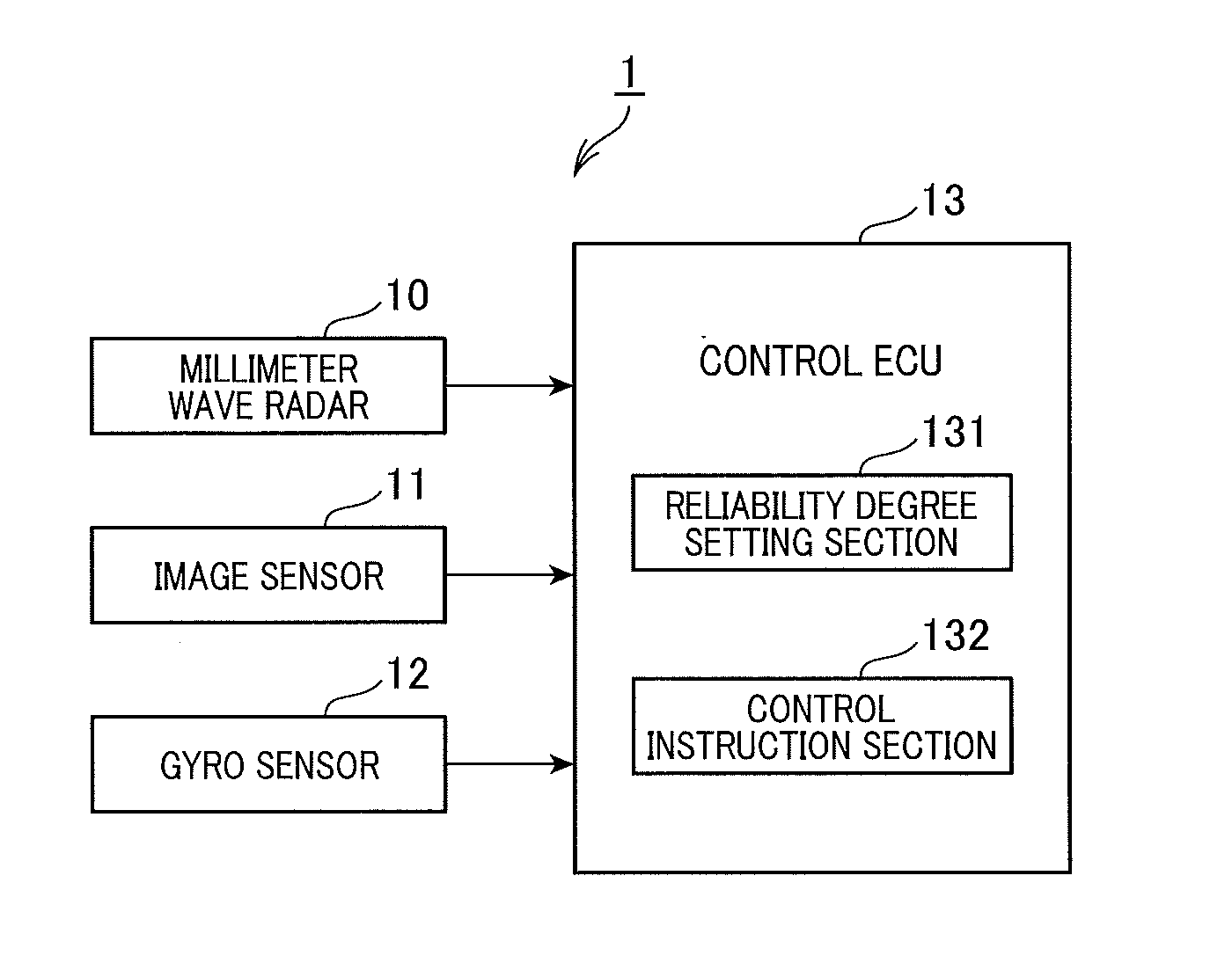
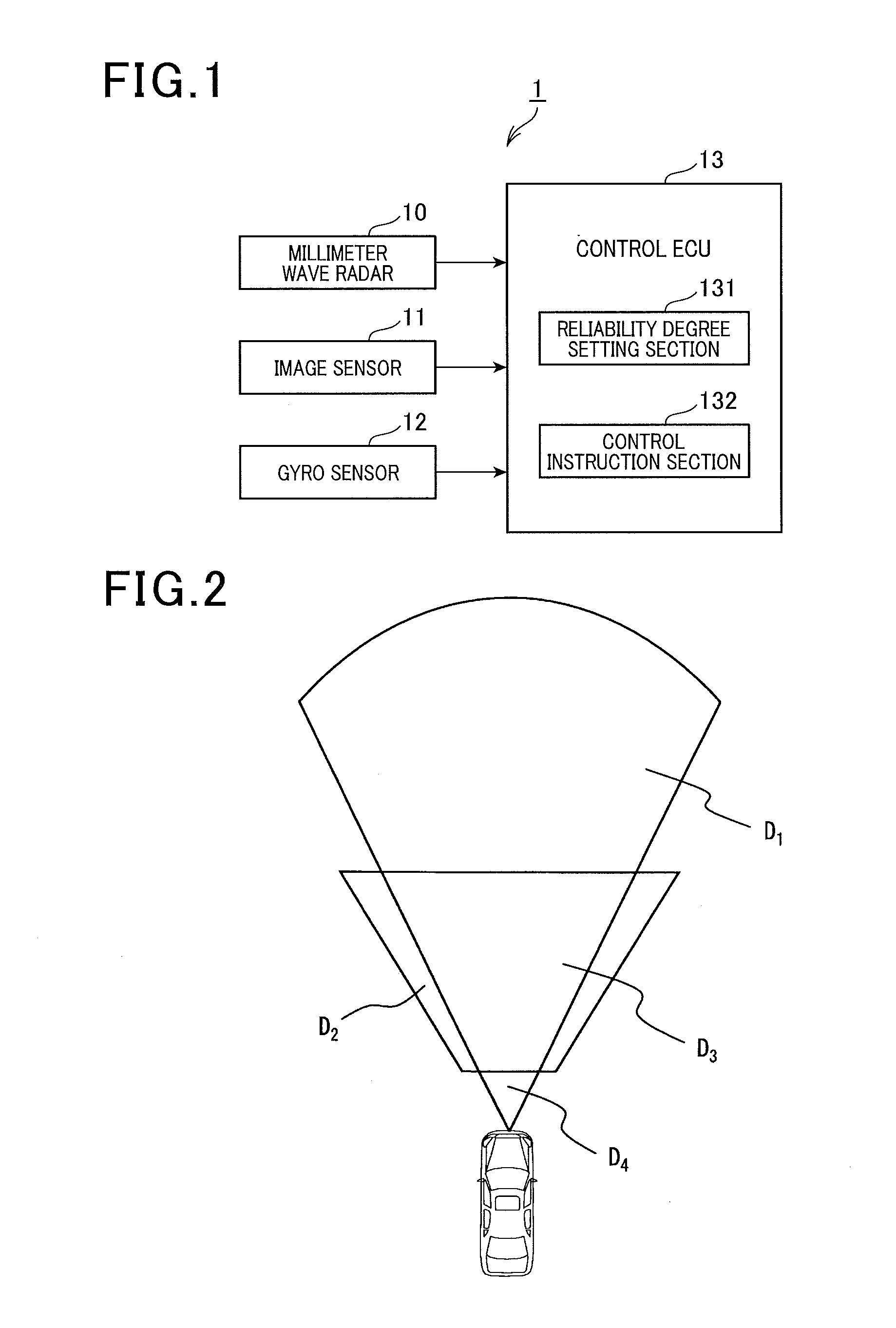
[0018]With reference to FIG. 1, a target detection apparatus 1 according to the first embodiment is described. The target detection apparatus 1 detects a target existing ahead of a vehicle, and is installed in the vehicle. FIG. 1 is a block diagram of the target detection apparatus 1. Hereinafter, the vehicle in which the target detection apparatus 1 is installed is referred to as “own vehicle”.

[0019]As shown in FIG. 1, the target detection apparatus 1 includes a millimeter wave radar 10 (first target detection means, first target detection section), an image sensor 11 (second target detection means, second target detection section), a gyro sensor 12 (turn detection means, turn detection section), and a control ECU 13.

[0020]The millimeter wave radar 10 transmits millimeter waves forward of the own vehicle at regular intervals (e.g. 50 ms), and detects a target based on waves reflected from the target existing ahead of the own vehicle. A target detection area D1 (see FIG. 2) of the m...


PUM


Abstract

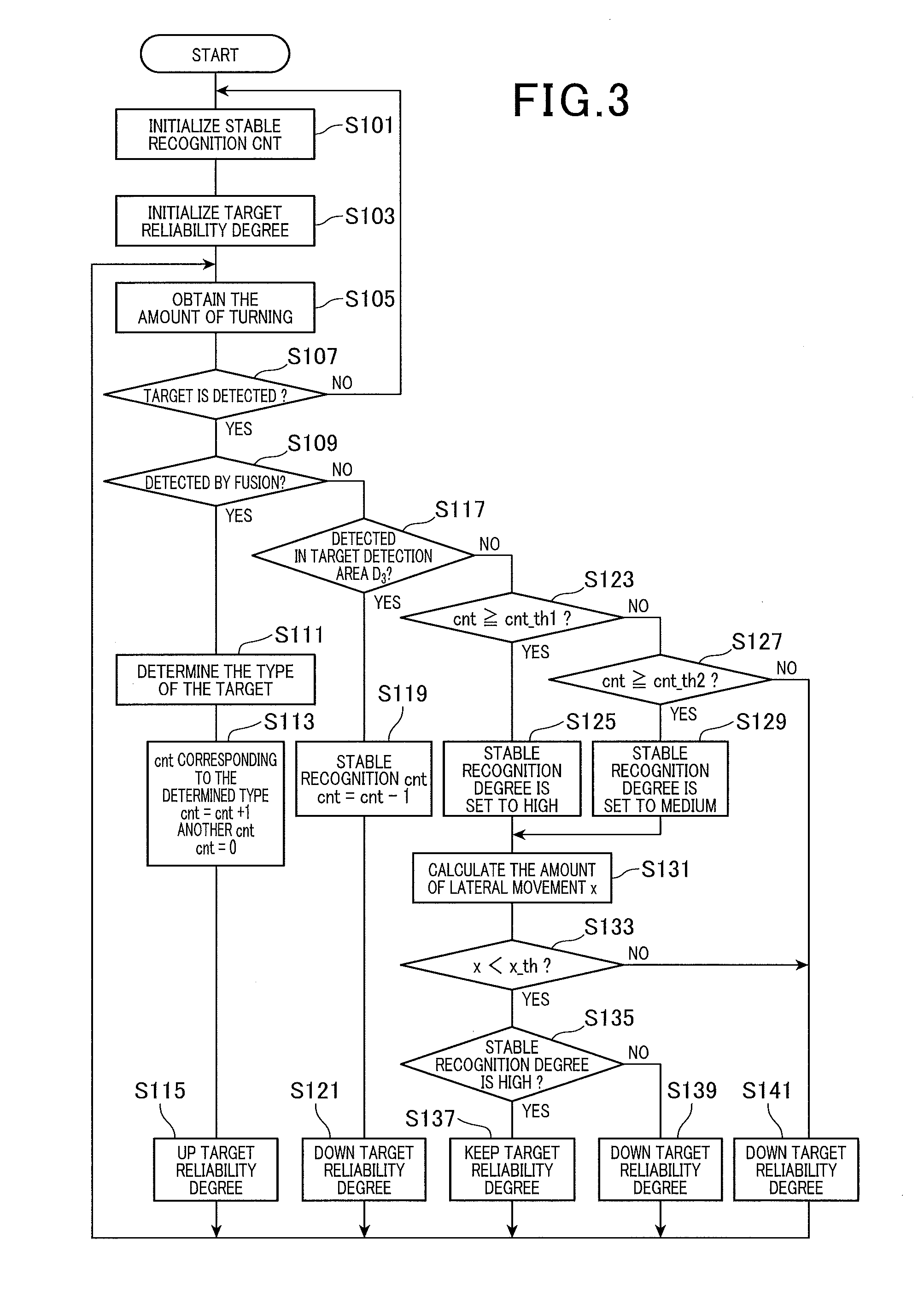
A target detection apparatus includes a first target detection section which detects a target which exists ahead of a vehicle and has a height sufficient to strike against the vehicle; a second target detection section which detects the target in an area different from an area in which the target is detected by the first target detection section, and a reliability degree setting section which sets a target reliability degree indicating probability that the target exists. When the target is detected only by the first target detection section or the second target detection section, and after the target is detected by both the first and the second target detection sections, the reliability setting section sets the target reliability degree based on an overlap detection time which is a period of time during which both the first and the second target detection sections continuously detect the target.

Description

CROSS-REFERENCE TO RELATED APPLICATION[0001]This application is based on and claims the benefit of priority from earlier Japanese Patent Application No. 2013-216627 filed Oct. 17, 2013, the description of which is incorporated herein by reference.BACKGROUND[0002]1. Technical Field[0003]The present invention relates to a target detection apparatus which detects a target positioned ahead of a vehicle by using a plurality of sensors.[0004]2. Related Art[0005]Conventionally, a technique is known which is for detecting a target existing in the area around a vehicle (for example, refer to JP-A-2001-99930). According to this technique, data obtained from a plurality of sensors are combined to correct information which is poor for individual data, thereby calculating a precise position of the detected target.[0006]The target detection apparatus disclosed in JP-A-2001-99930 detects a target by using a millimeter wave radar and an image sensor. Regarding the target existing in a predetermined...

Claims


Application Information

Patent Timeline
Patent Type & Authority Applications(United States)
IPC IPC(8): G01S13/04G01S13/93G01S13/931
CPCG01S13/931G01S13/04G01S13/86G01S13/93G01S13/867G01S7/41G01S13/66G01S7/2955
Inventor TAKAKI, RYO
Owner DENSO CORP
Learn More