
Photovoltaic module and use thereof

a photovoltaic module and photovoltaic technology, applied in photovoltaics, photovoltaic energy generation, electrical equipment, etc., can solve the problems that large-area photovoltaic modules providing correspondingly high energy output will no longer be reasonably available in transportable form and/or readily usable, and achieve the effect of simple wiring

Inactive Publication Date: 2015-03-26
AT & S AUSTRIA TECH & SYSTTECHN AKTIENGES
View PDF2 Cites 43 Cited by
  • Summary
  • Abstract
  • Description
  • Claims
  • Application Information

AI Technical Summary

Benefits of technology

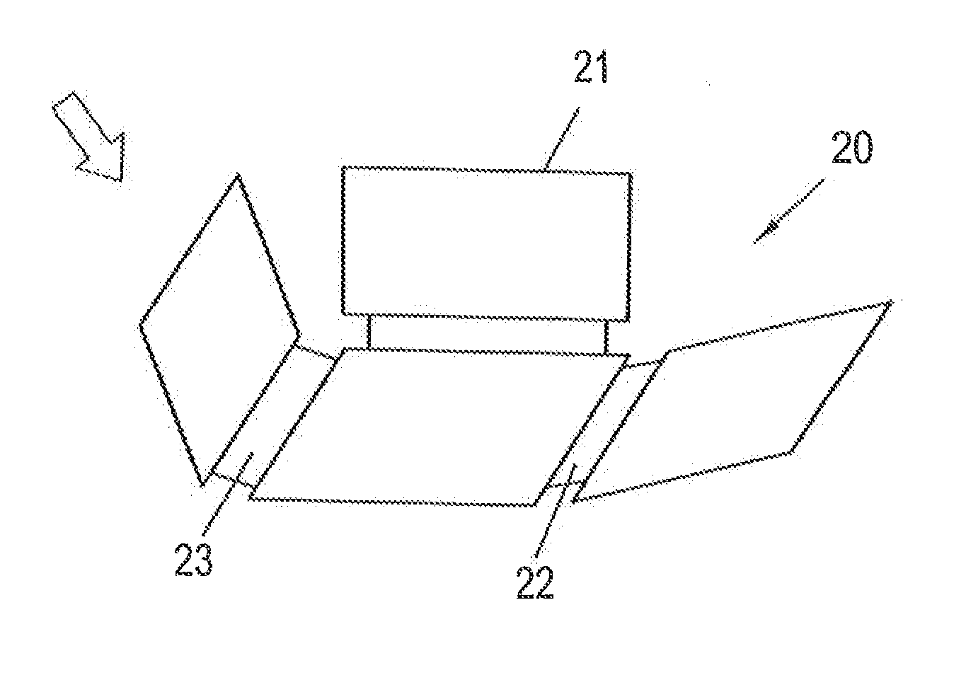
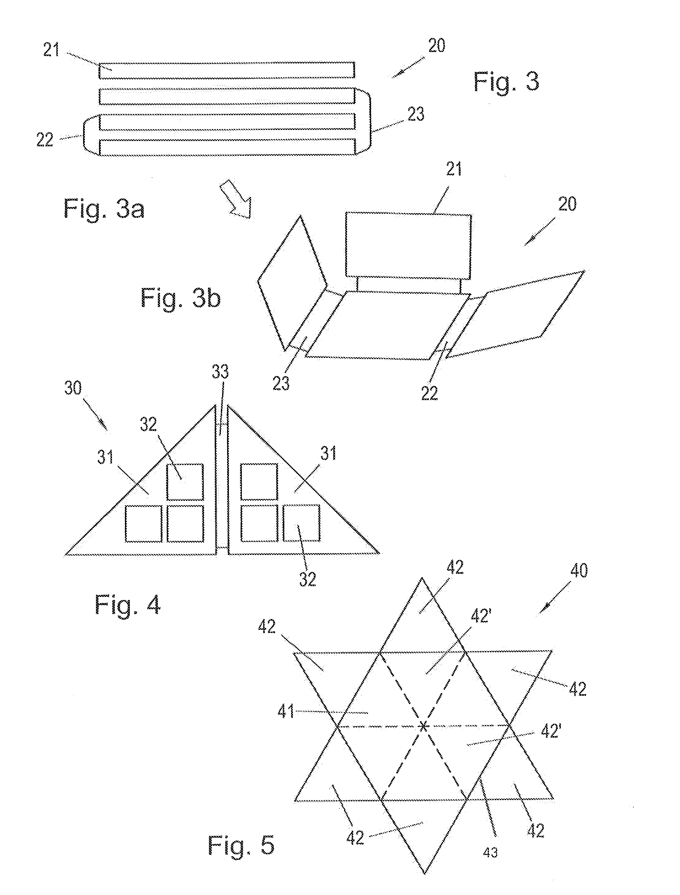
The present invention provides a photovoltaic module that overcomes the problems of prior art by reducing the size of the module in its transport position and enabling simple wiring between solar cells. The module is formed with a flexible connecting region between subregions, which can be arranged in a position that optimizes energy generation. The subregions can also be controlled individually to prevent overheating and optimize performance. The dimensions of the flexible connecting regions between subregions are proposed to be a multiple of the thickness of the subregion. Overall, the invention provides a portable and easily transportable photovoltaic module with improved performance and reliability.

Problems solved by technology

While, when mounting such photovoltaic modules, for instance, on building parts, in particular roof surfaces, an appropriately safe and reliable anchorage and retention or support of such large-area photovoltaic modules are possible, it is immediately apparent that large-area photovoltaic modules providing a correspondingly high energy output will no longer be reasonably available in a transportable form and / or readily usable and, optionally, simply mountable or dismountable form, bearing in mind, in particular, their large and unwieldy dimensions as well as their possibly high weights.

Method used


Image

  • Photovoltaic module and use thereof
  • Photovoltaic module and use thereof
  • Photovoltaic module and use thereof

Examples


Embodiment Construction

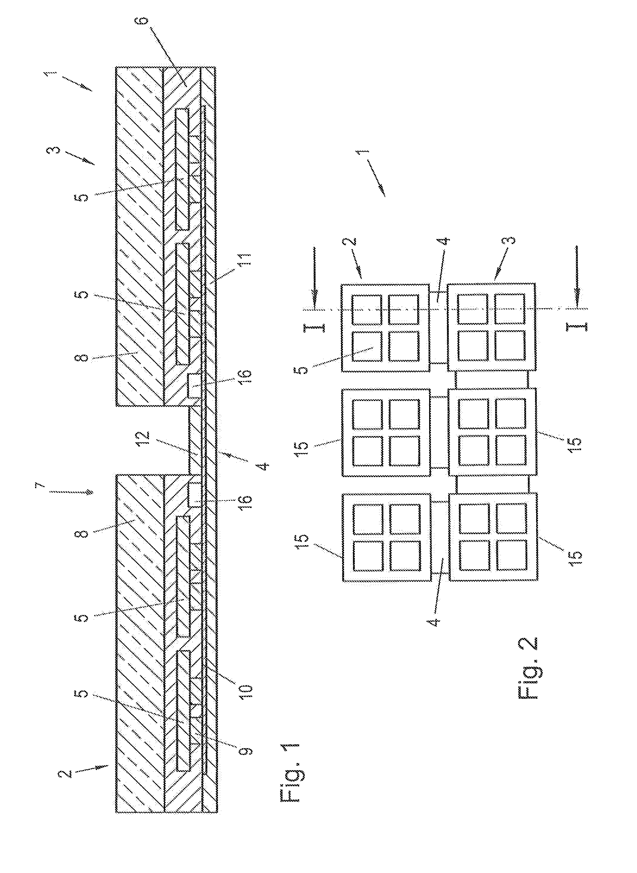
[0023]FIG. 1 depicts a section through a photovoltaic module 1, from which it is apparent that subregions 2 and 3 of the photovoltaic module are coupled or connected to each other via a flexible connecting region denoted by 4.

[0024]Each of the subregions 2 and 3 of the photovoltaic module 1 comprises a plurality of solar cells 5, which are embedded in a layer 6 of synthetic material consisting, for instance, of ethylene vinyl acetate. The solar cells 5 are, moreover, covered by a transparent cover layer 8 made, for instance, of glass in the direction towards an irradiation environment schematically indicated by 7.

[0025]For discharging the electrical energy generated in the solar cells 5, the latter are connected to an electrically conducting or conductive and structured layer or structure 10 via contacts schematically indicated by 9, said discharging of energy being effected via a connection housing (not illustrated) using the conducting layer or structure 10.

[0026]A cover film or l...


PUM


Abstract

In the case of a photovoltaic module which comprises a plurality of solar cells which are each coupled to an electrically conductive, structured layer for discharging the electrical energy generated in the solar cells, wherein at least two subregions of the photovoltaic module are coupled to one another via a flexible connecting region, provision is made for the solar cells to be coupled on the rear side of said solar cells to the electrically conductive, structured layer, and for the electrically conductive, structured layer to be integrated in a multilayered film arranged on the rear side of the solar cells, wherein the multilayered film forms the flexible connecting region between the at least two subregions of the photovoltaic module, as a result of which a photovoltaic module which can be tilted or folded can be made available.

Description

[0001]This is a national stage of PCT / AT2012 / 000154 filed Jun. 5, 2012 and published in German, which has a priority of Austria no. GM 327 / 2011 filed Jun. 7, 2011, hereby incorporated by reference.FIELD OF THE INVENTION[0002]The present invention relates to a photovoltaic module which comprises a plurality of solar cells that are each coupled to an electrically conducting or conductive and structured layer or structure for discharging the electrical energy generated in the solar cells, wherein at least one transparent carrier layer is provided on the surface of the solar ceils facing away from the electrically conducting layer or structure, wherein the electrically conducting and structured layer or structure can be contacted with connections of a connection housing, wherein at least two subregions of the photovoltaic module which each have at least one solar cell are coupled to one another via a flexible connecting region and can be folded or tilted along the flexible connecting re...

Claims


Application Information

Patent Timeline
IPC IPC(8): H02S30/20H01L31/02
CPCH01L31/0201H02S30/20H01L31/048H01L31/0516Y02E10/50
Inventor GMUNDNER, GERNOT
Owner AT & S AUSTRIA TECH & SYSTTECHN AKTIENGES
Learn More