
Bearing structure

Inactive Publication Date: 2015-03-19
CHEN NIEN CHI
View PDF6 Cites 4 Cited by
  • Summary
  • Abstract
  • Description
  • Claims
  • Application Information

AI Technical Summary

Benefits of technology

The aim of this patent is to enhance the bearing structure.

Problems solved by technology

However, if the shaft is unexpectedly rotated at another direction, the unidirectional bearing would be broken.

Method used


Image

  • Bearing structure
  • Bearing structure
  • Bearing structure

Examples


Embodiment Construction

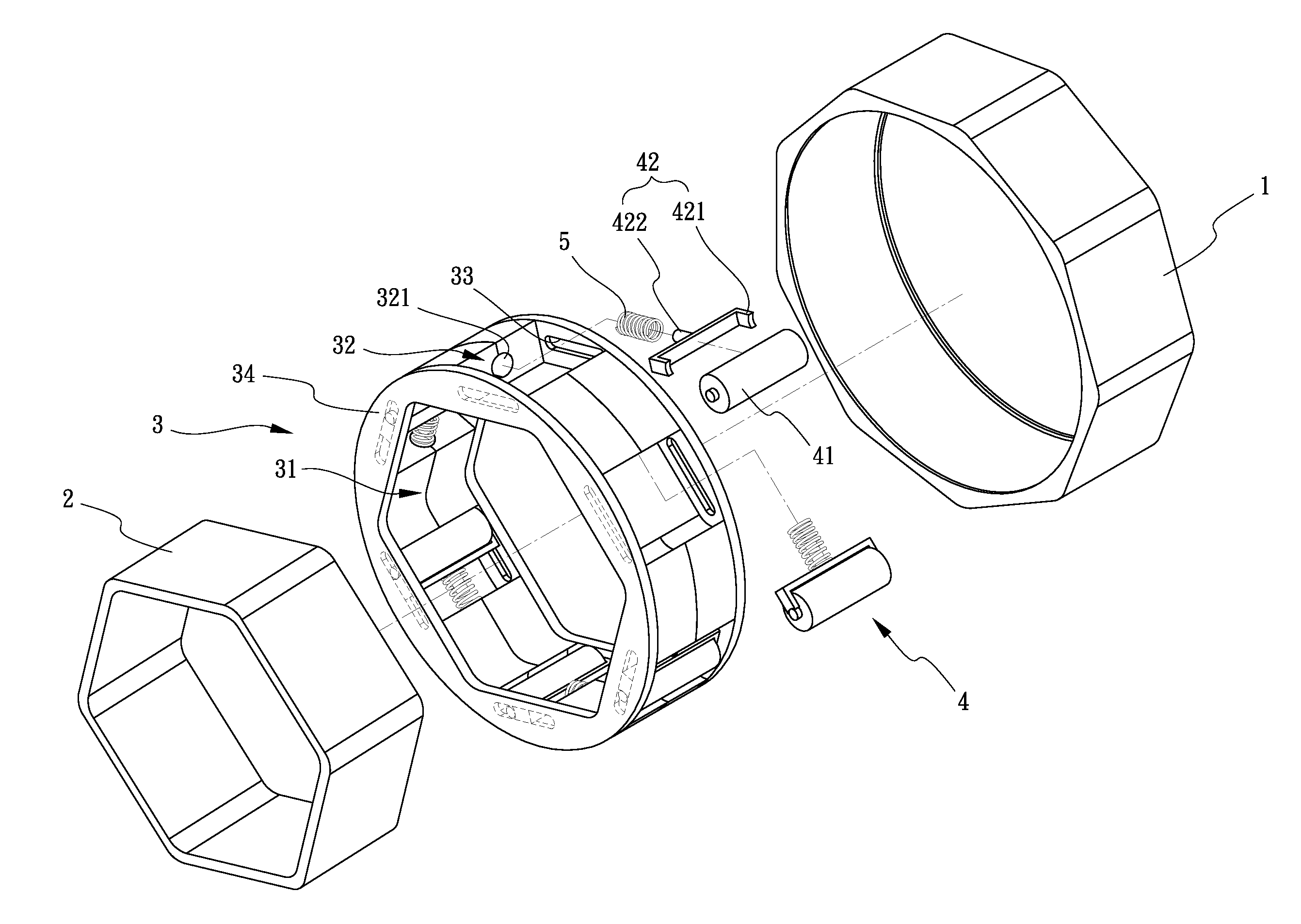
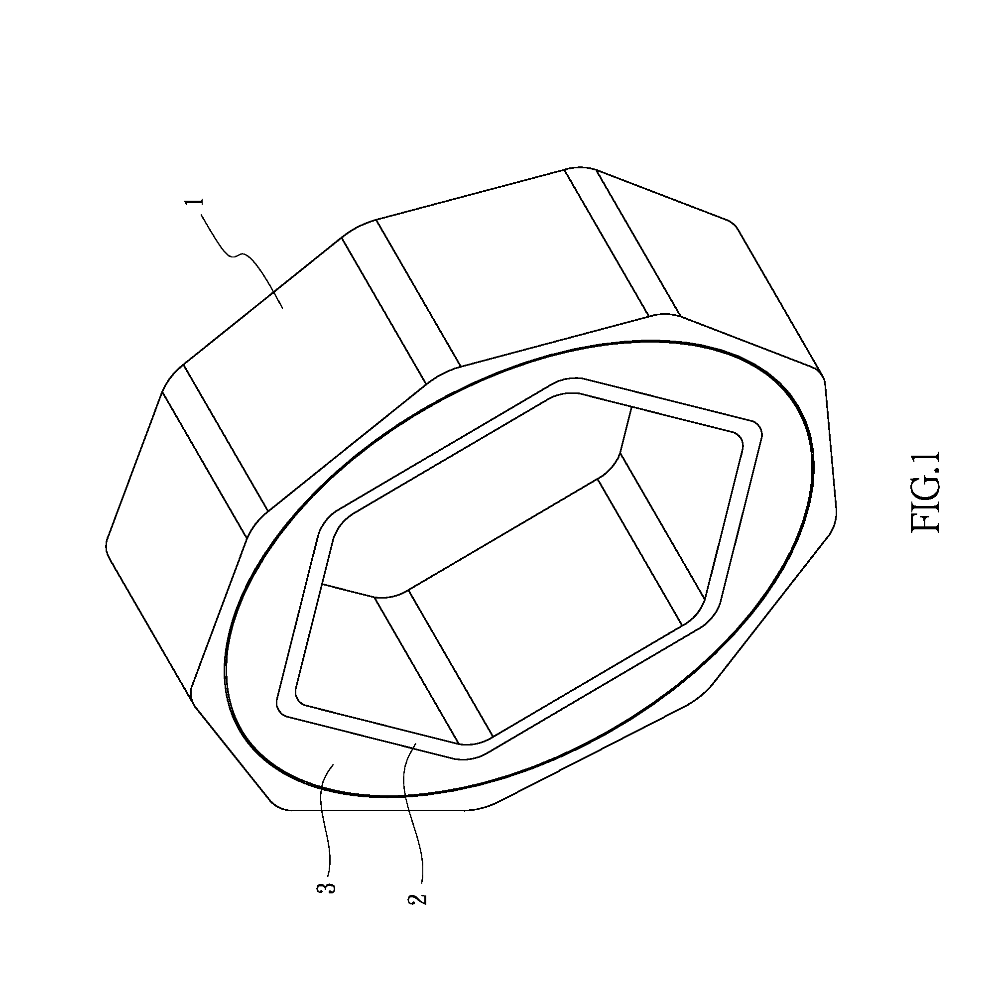
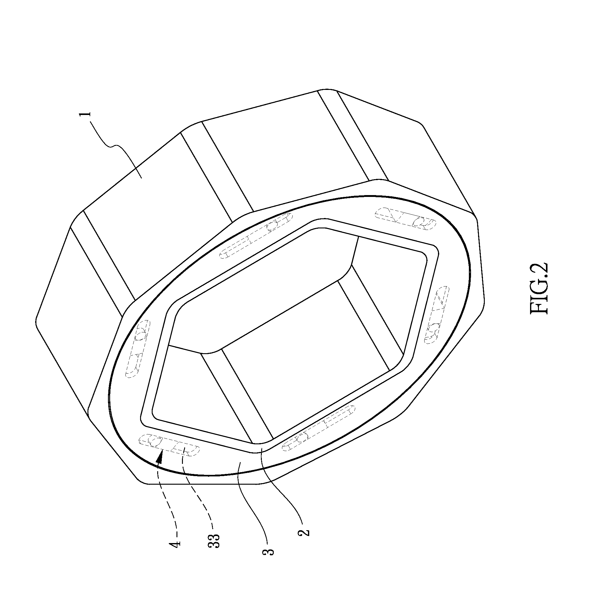
[0017]Referring to FIGS. 1-4, a bearing structure in accordance with the present invention comprises an outer ring 1, an inner ring 2, a middle base 3 and a plurality of roller sets 4. The inner ring 2 is hexagon-shaped. The middle base 3 is sandwiched in between the outer ring 1 and the inner ring 2. The middle base 3 is assembled at a center of the outer ring 1. The middle base 3 has an assembling hole 31 opened at a center thereof. A shape of the assembling hole 31 is the same as a shape of the inner ring 2. The assembling hole 31 and the inner ring 2 are both polygonal. The inner ring 2 is assembled in the assembling hole 31. A rotation of the inner ring 2 drives the middle base 3 to rotate. The rotation of the middle base 3 drives the outer ring 1 to rotate. The middle base 3 has a plurality of positioning openings 32 opened on a wall of the assembling hole 31 therethrough. Each two adjacent positioning openings 32 are spaced from each other. Each positioning opening 32 has two...


PUM


Abstract

A bearing structure includes an outer ring, an inner ring, a middle base and a plurality of roller sets, the middle base sandwiched in between the outer ring and the inner ring, the middle base assembled at the outer ring, the middle base having an assembling hole opened at a center thereof, the inner ring assembled in the assembling hole, the middle base having a plurality of positioning openings opened on a wall of the assembling hole therethrough, each positioning opening having two grooves defined at two opposite walls thereof, each roller set assembled in each positioning opening, two ends of each roller set respectively inserted into the two grooves of each positioning opening, an elastomer assembled in each positioning opening, the elastomer located between the two grooves, two ends of the elastomer respectively abutting against another wall of each positioning opening and one end of each roller set.

Description

BACKGROUND OF THE INVENTION[0001]1. Field of the Invention[0002]The present invention relates to a structure and more particularly to a bearing structure.[0003]2. Description of Related Art[0004]A bearing is a machine element that constrains relative motion between moving parts to only the desired motion. The design of the bearing may, for example, provide for free linear movement of the moving part or for free rotation around a fixed axis; or, it may prevent a motion by controlling the vectors of normal forces that bear on the moving parts. Many bearings also facilitate the desired motion as much as possible, such as by minimizing friction. Bearings are classified broadly according to the type of operation, the motions allowed, or to the directions of the loads (forces) applied to the parts. Specially, a unidirectional bearing only allows a shaft to rotate at one direction; in other words, a rotation at another direction of the shaft is prohibited.[0005]However, if the shaft is une...

Claims


Application Information

Patent Timeline
IPC IPC(8): F16D41/064F16D41/06
CPCF16D41/06F16D41/064F16D41/067F16D2041/0608
Inventor CHEN, NIEN-CHI
Owner CHEN NIEN CHI
Learn More