Intrauterine device

a technology of intrauterine devices and uterine spirals, which is applied in the field of medical devices, can solve problems such as disruption or collapse of uterine spiral arteries, and achieve the effects of preventing migration of intrauterine devices, promoting contraception, and promoting contraception

Active Publication Date: 2015-03-12
SEBELA VLC LTD
View PDF3 Cites 1 Cited by
  • Summary
  • Abstract
  • Description
  • Claims
  • Application Information

AI Technical Summary

Benefits of technology

[0011]In one aspect of the present invention, a method is described for promoting contraception by applying force against an inner wall of a uterus without blocking the fallopian tubes. The method may involve advancing a distal end of a delivery device through a cervix, advancing an intrauterine device out of the distal end of the delivery device and into the uterus, and removing the delivery device. Advancing the intrauterine device out of the delivery device causes it to expand into an expanded configuration to cause two tissue contact members of the intrauterine device to move in approximately opposite directions to contact and apply force against the inner wall of the uterus. Each of the tissue contact members, when the intrauterine device is delivered, is positioned near, but not within, an opening of a fallopian tube. The two tissue contact members apply sufficient force against the uterine wall to promote contraception and prevent migration of the intrauterine device out of the uterus or into the fallopian tubes.
[0013]In some embodiments, the method may further involve causing a disruption or collapse of the uterine spiral arteries using the tissue contact members. Some embodiments may optionally further involve causing a localized ischemia to endometrial tissue of the uterus using the tissue contact members. The method may also involve preventing tissue in-growth, uterine wall perforation, and migration of the tissue contact members by providing the tissue contact members with a material, size and shape that resist in-growth, perforation and migration.

Problems solved by technology

In some embodiments, the method may further involve causing a disruption or collapse of the uterine spiral arteries using the tissue contact members.

Method used


Image

  • Intrauterine device
  • Intrauterine device
  • Intrauterine device

Examples


Embodiment Construction

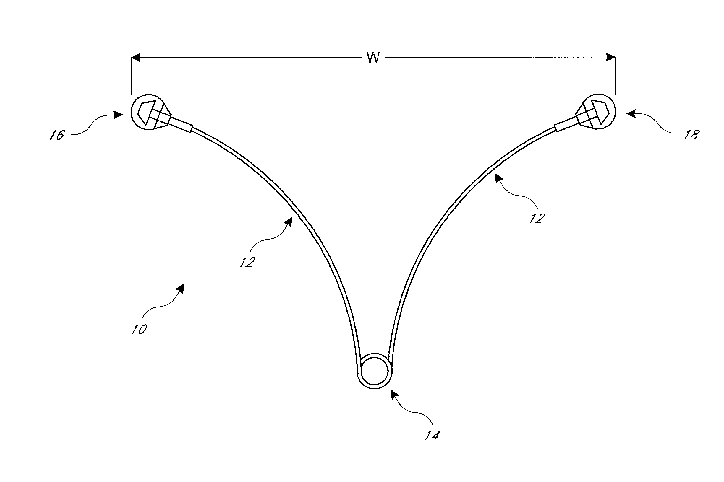
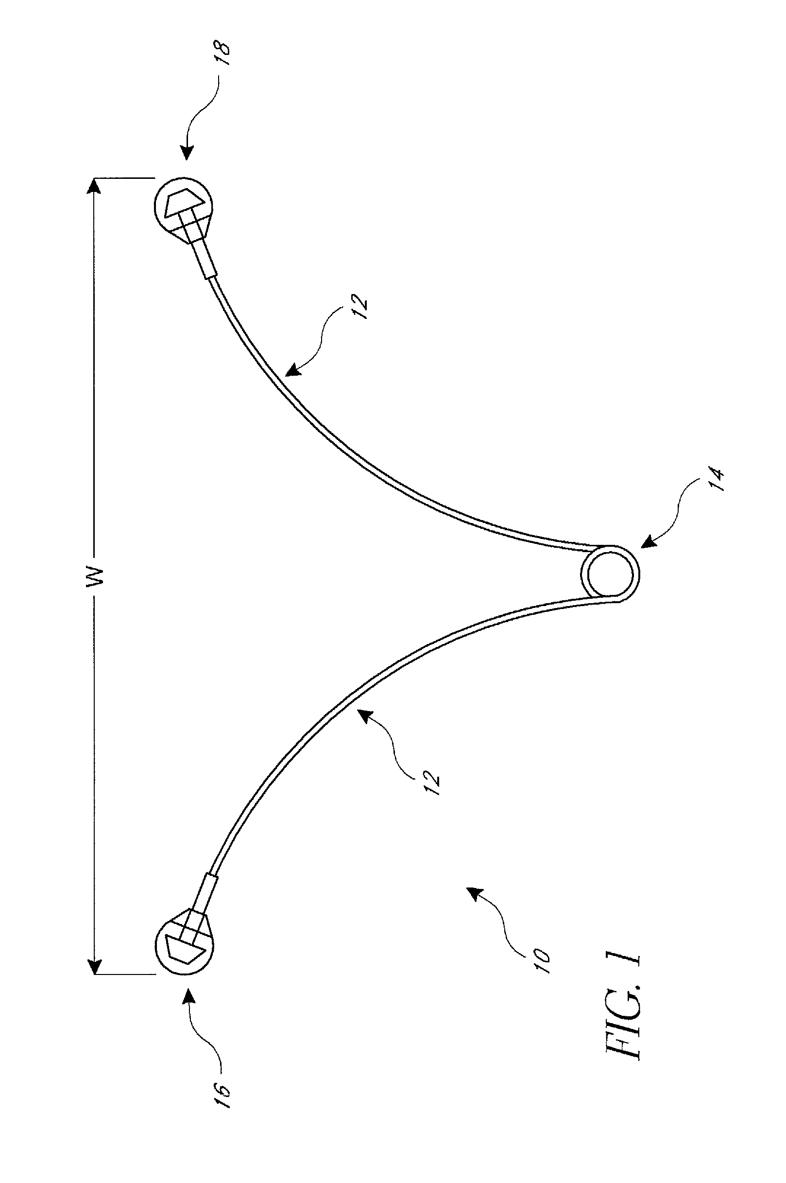
[0056]Referring to FIG. 1, in one embodiment, an intrauterine device (IUD) 10 may include a resilient, elongate member 12 and two tissue contact members 16, 18 disposed at opposite ends of elongate member 12. Elongate member 12 may include a spring portion 14, typically disposed approximately at a midpoint between the opposite ends of elongate member 12. Elongate member 12 is manufactured from a resilient material, such as but not limited to Nitinol (nickel titanium alloy), and has a default (or “predetermined”) expanded configuration as shown in FIG. 1. Elongate member 12 may be compressed into a low profile, collapsed configuration, to facilitate delivery of IUD 10 through a cervix, typically using a delivery device. When released from compression within the uterus, IUD 10 springs back into its default expanded configuration to allow tissue contact members 16, 18 to contact and apply force against the uterine wall.

[0057]As illustrated in FIG. 1, in one embodiment, IUD 10 has a gen...


PUM


Abstract

An intrauterine device for applying force to a wall of a uterus to promote contraception without blocking the fallopian tubes may include an elongate member formed of a resilient material and having a default expanded configuration and a spring portion disposed approximately at a midpoint between two ends of the elongate member. The IUD may also include two tissue contact members, one tissue contact member disposed at one of the two ends of the elongate member and the other tissue contact member disposed at the other end. The tissue contact members may generate a laterally directed force against the wall of the uterus when the intrauterine device assumes its default expanded configuration.

Description

CROSS-REFERENCE TO RELATED APPLICATIONS[0001]This application is a continuation of U.S. patent application Ser. No. 13 / 294,091, entitled “Intrauterine Device” which was filed on Nov. 10, 2011, which is a continuation-in-part of U.S. patent application Ser. No. 12 / 856,876 (Pub. No. 2010 / 0300452), now U.S. Pat. No. 8,662,081, entitled “Intrauterine Device” which was filed on Aug. 16, 2010, the full disclosures of which are hereby incorporated by reference.BACKGROUND OF THE INVENTION[0002]1. Field of the Invention[0003]The invention relates generally to medical devices. More specifically, the invention relates to an intrauterine device and method for use.[0004]2. Description of the Related Art[0005]Intrauterine devices (IUDs) are a commonly used form of contraception. Generally, IUDs are believed to work by producing a spermicidal environment in the uterus and thus preventing fertilization of the egg by sperm. They may also have a post-fertilization effect, but IUDs are generally belie...

Claims


Application Information

Patent Timeline
Patent Type & Authority Applications(United States)
IPC IPC(8): A61F6/14A61F6/18
CPCA61F6/18A61F6/144A61F6/142A61F6/20
Inventor TAL, MICHAEL G.GUTELIUS, PATRICK N.DEBISSCHOP, MARK J.SHIKHMAN, OLEGPATRIZIO, PASQUALEKATZ, BOB H.
Owner SEBELA VLC LTD
Why Eureka
Try Eureka