
Protective Element

a protective element and textile material technology, applied in the field of protective elements, can solve the problems of cutting teeth affecting the clothing of users, affecting the and affecting the use of protective clothing, etc., to achieve the effect of improving wear comfort, easy production and forming, and high comfort of wearing a protective element composed of textile materials

Active Publication Date: 2015-03-05
ANDREAS STIHL AG & CO KG
View PDF4 Cites 0 Cited by
  • Summary
  • Abstract
  • Description
  • Claims
  • Application Information

AI Technical Summary

Benefits of technology

The patent text describes a cutter bar or shears that use a special material to slow down cutting to protect the surface from damage. The material is made of a fabric layer that is stretched out and folded, making a barrier to prevent the cut from spreading. This protective barrier also prevents the cut from getting into the fabric layer underneath. The text also mentions that the material is made of textile material, which is comfortable and easily produced. The technical effect of this text is to provide a means to protect surfaces from cutting damage while also offering wearing comfort.

Problems solved by technology

When operating hand-guided power tools such as hedge trimmers, the cutting teeth may damage the clothing of the user in case of improper power tool handling.
Under unfavorable conditions, however, fabric layers that are underneath the cut-retardant protective material may be gripped and damaged during blockage of the cutting blades.

Method used


Image

  • Protective Element
  • Protective Element
  • Protective Element

Examples


Embodiment Construction

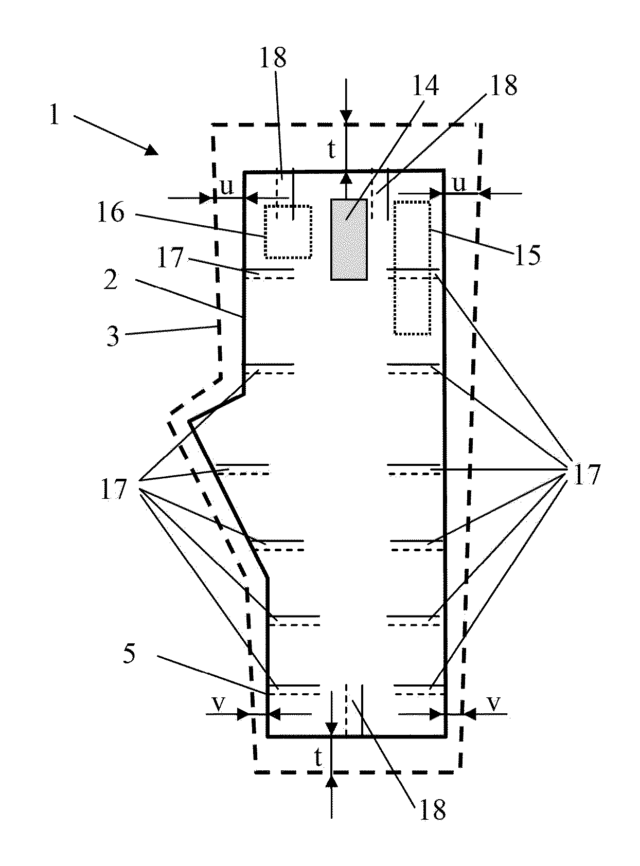
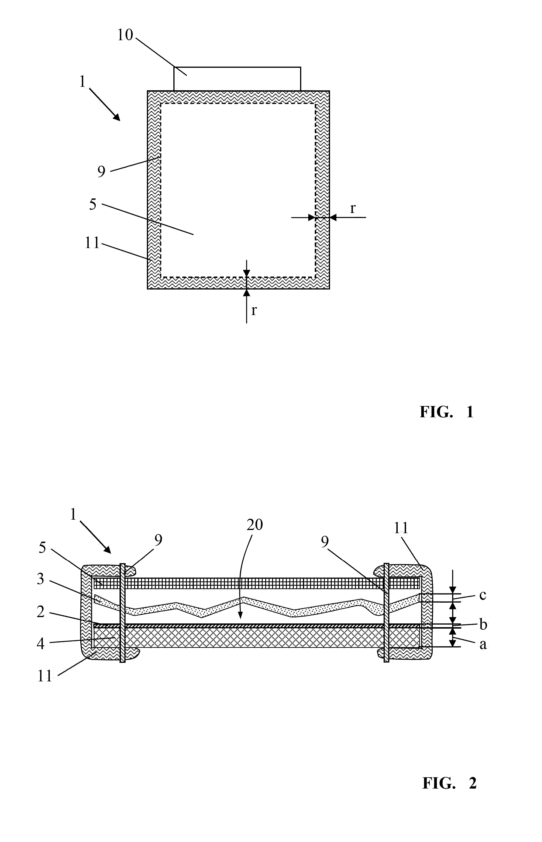
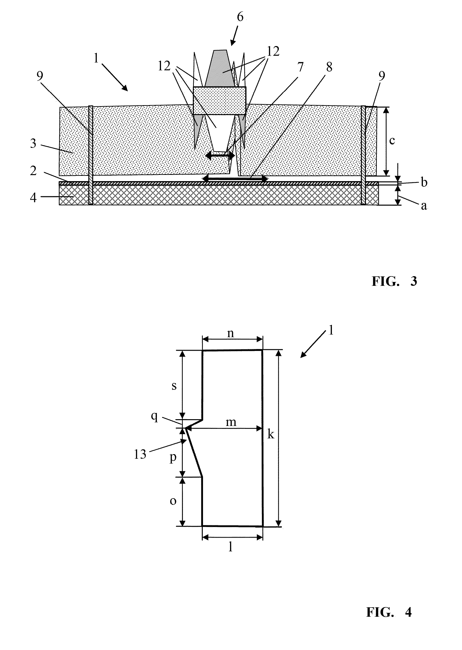
[0028]FIG. 1 shows an exemplary embodiment of a protective element 1 according to the invention. In FIG. 1, the embodiment of the protective element 1 has a substantially rectangular contour. The shape of the protective element 1 depends on which body part of the user is to be protected and can deviate from the illustrated rectangular cross-sectional shape. The protective element 1 is comprised of several material layers that are resting flat on each other. The material layers are connected to each other by means of at least one fastening location 9. The fastening location 9 is a seam in the illustrated embodiment. The yarn which is used for the seam extends in the illustrated embodiment circumferentially at an edge spacing r that is in particular constant and amounts to approximately 1 cm relative to the outer boundary of the protective element 1. Expediently, on the outer edge of the protective element 1 a bordering tape 11 is arranged. The bordering tape 11 encloses all material ...


PUM

PropertyMeasurementUnit
thicknessaaaaaaaaaa
thickaaaaaaaaaa
thicknessaaaaaaaaaa

Abstract

A protective element is provided with a flat first material layer of a low-fold material and a flat second material layer of a folded cut-retardant material. A surface area of the second material layer in a stretched-out state is 1.2 to 2.5 times greater than a surface area of the first material layer in a stretched-out state. The second material layer is placed in a gathered state onto the first material layer. The first material layer forms a gliding layer for the second material layer.

Description

BACKGROUND OF THE INVENTION[0001]The invention relates to a protective element comprising at least two flat material layers which are used as an insert in a protective element or in protective clothing.[0002]When operating hand-guided power tools such as hedge trimmers, the cutting teeth may damage the clothing of the user in case of improper power tool handling. For safety reasons, it is therefore recommended that the user wear protective clothing with cut-retardant function.[0003]When operating hedge trimmers, the cutting blades of the cutter bar perform a complex movement sequence and thereby clamp and cut the object to be cut, for example, branches and twigs of a hedge or the like, so that finally the object is cut through. When in operation the moving cutting blades contact protective clothing, the cutting blades of the cutter bar are blocked by a cut-retardant insert so that cutting through the protective clothing is substantially prevented. Under unfavorable conditions, howev...

Claims


Application Information

Patent Timeline
Patent Type & Authority Applications(United States)
IPC IPC(8): A41D31/00A41D1/06
CPCA41D31/0061A41D1/06A41D31/0016A41D31/245A41D2600/20Y10T428/24802A41D31/145
Inventor STRAUSS, PETRA
Owner ANDREAS STIHL AG & CO KG
Learn More