
Apparatus for measuring temperature distribution across the sole of the foot

a technology for measuring the temperature distribution of the sole of the foot, which is applied in the field of maintaining the health of the foot, and can solve the problems of gangrene, leg amputation, and serious health complications

Inactive Publication Date: 2015-02-26
PODIMETRICS
View PDF29 Cites 51 Cited by
  • Summary
  • Abstract
  • Description
  • Claims
  • Application Information

AI Technical Summary

Benefits of technology

The patent describes an apparatus for measuring the temperature distribution on the sole of a human foot using a flexible substrate that can bend without breaking. The substrate has multiple discontinuities that cause it to have elastic properties, allowing it to recover its size and shape after deformation. Sensor regions on the substrate can move relative to each other when subjected to a mechanical force. The flexible substrate can be made of a bendable circuit board material or traditional circuit material and can include a plurality of non-uniformly spaced resistive temperature sensors. An open platform version of the apparatus is also described. Overall, the invention provides a better method for measuring temperatures on the foot for various applications such as medical diagnosis or fitness analysis.

Problems solved by technology

Open sores on an external surface of the body often form septic breeding grounds for infection, which can lead to serious health complications.
For example, foot ulcers on the bottom of a diabetic's foot can lead to gangrene, leg amputation, or, in extreme cases, death.
Unfortunately, known techniques for monitoring foot ulcers, among other types of ulcers, often are inconvenient to use, unreliable, or inaccurate, thus reducing compliance by the very patient populations that need it the most.

Method used


Image

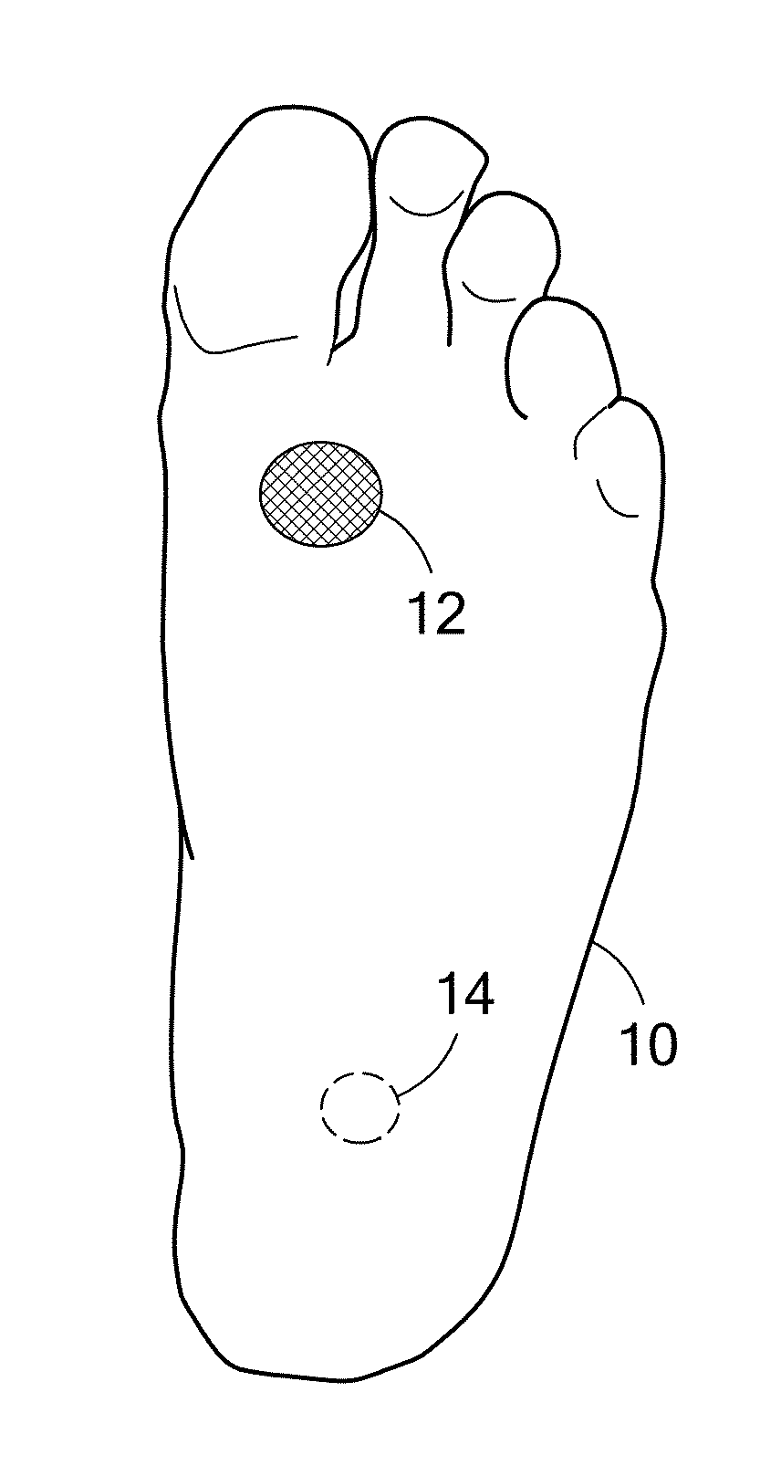
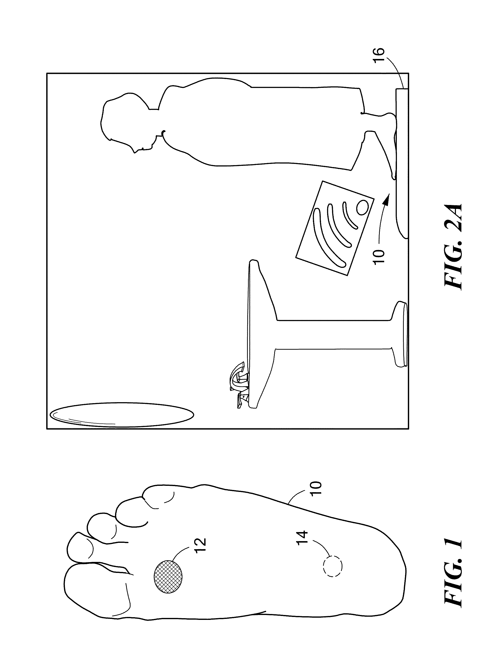
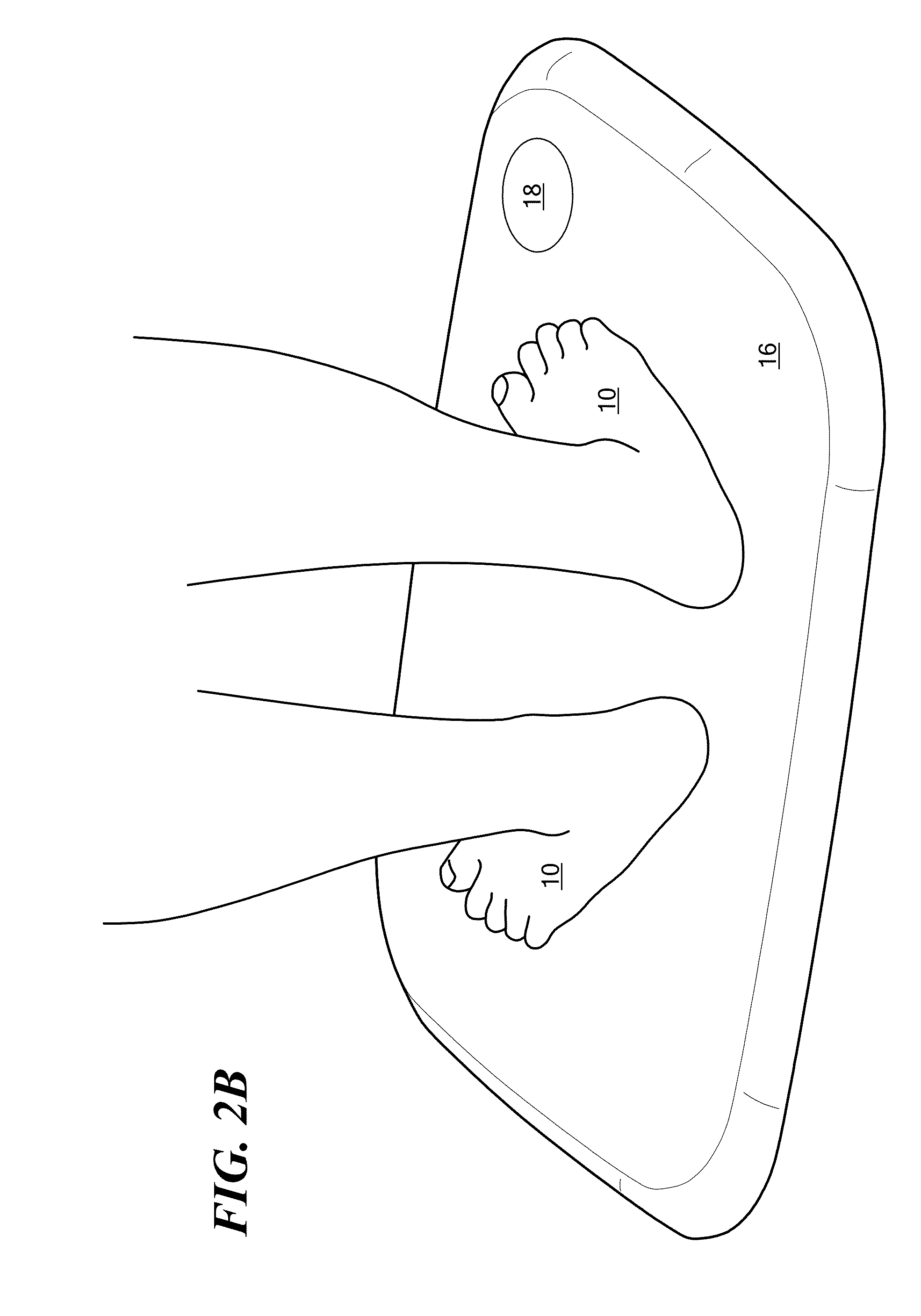
  • Apparatus for measuring temperature distribution across the sole of the foot
  • Apparatus for measuring temperature distribution across the sole of the foot
  • Apparatus for measuring temperature distribution across the sole of the foot

Examples


Embodiment Construction

[0008]In accordance with one embodiment of the invention, an apparatus for measuring the temperature distribution over the sole of the foot has a flexible substrate formed at least in part from a substrate material configured to be bendable without breaking when receiving the sole of a human foot. The substrate defines a plurality of discontinuities forming a plurality of substrate segments. Each substrate segment has a sensor region with a surface for coupling a sensor, and at least one connector to connect to at least one sensor region of an adjacent substrate segment. Each of a plurality of the sensor regions is configured to be movable relative to other sensor regions when subjected to a mechanical force applied to its surface. The discontinuities cause the flexible substrate to exhibit elastic properties in the aggregate so that it can recover its size and shape after deformation along one or more of the discontinuities.

[0009]The apparatus also has a plurality of resistive temp...


PUM


Abstract

An apparatus for measuring the temperature distribution over the sole of the foot has a flexible substrate. The substrate defines a plurality of discontinuities forming a plurality of substrate segments. Each substrate segment has a sensor region with a surface for coupling a sensor, and at least one connector to connect to at least one sensor region of an adjacent substrate segment. Each of a plurality of the sensor regions is configured to be movable relative to other sensor regions. The discontinuities cause the flexible substrate to exhibit elastic properties in the aggregate. The apparatus also has a plurality of resistive contact temperature sensors coupled with the flexible substrate.

Description

PRIORITY[0001]This patent application claims priority from provisional U.S. patent application No. 61 / 869,990 filed Aug. 26, 2013, entitled, “SENSOR MATRIX FOR MEASURING PROPERTIES OF A THREE-DIMENSIONAL BODY,” and naming David Robert Linders as inventor, the disclosure of which is incorporated herein, in its entirety, by reference.RELATED APPLICATIONS[0002]This patent application is related to the following utility patent applications, each of which is incorporated herein, in its entirety, by reference:[0003]1. U.S. patent application Ser. No. 13 / 799,828, filed on Mar. 13, 2013, entitled, “METHOD AND APPARATUS FOR INDICATING THE RISK OF AN EMERGING ULCER,” assigned attorney docket number 3891 / 1001, and naming Jonathan David Bloom, David Robert Linders, Jeffrey Mark Engler, Brian Petersen, Adam Geboff, AND David Charles Kale, and as inventors,[0004]2. U.S. patent application Ser. No. 13 / 803,866, filed on Mar. 14, 2013, entitled, “METHOD AND APPARATUS FOR INDICATING THE EMERGENCE OF ...

Claims


Application Information

Patent Timeline
IPC IPC(8): A61B5/01G01K7/16A61B5/00
CPCA61B5/015G01K7/16A61B5/6829G01K1/026G01K2213/00A61B5/6892A61B5/6807G01K13/20A43B3/34
Inventor LINDERS, DAVID ROBERTPETERSEN, BRIAN
Owner PODIMETRICS
Learn More