
Source routing in multicast transmissions

Active Publication Date: 2015-02-19
VERIZON PATENT & LICENSING INC
View PDF5 Cites 53 Cited by
  • Summary
  • Abstract
  • Description
  • Claims
  • Application Information

AI Technical Summary

Benefits of technology

The patent text describes a technology for distributing information from one network location to multiple devices at different locations. This technology uses a multicast distribution tree to forward data packets from a source device to multiple receiver devices. The patent also describes various methods for controlling the routing of data for multicasting, such as the use of routing protocols and multicast forwarding tables. The technical effects of this technology include reducing the overhead of creating and managing connections between devices, improving reliability, and reducing latency in delivering information.

Problems solved by technology

However, the overhead incurred with creating and managing a connection between a sending device and a number of receiving devices may be prohibitively expensive when a large number of receiving devices are included.
It is therefore understood that source tree implementations incur a cost of maintaining additional multicast state information in the multicast network.
However, the shared tree may incur routing inefficiencies because multicast traffic from each source device must travel to the common point and then follow a path to each of the receiver devices.
Thus, in a shared tree implementation, there is a tradeoff between optimal routing and the amount of state information that is maintained.
Moreover, another tradeoff may be a reduction in bandwidth efficiency by routing all multicast traffic to the common point and then having the network device at the common point determine a forwarding decision(s) for the multicast data.
This results in a tradeoff of dedicating an amount of data bandwidth for including information related to a distribution tree state in the data packets.

Method used


Image

  • Source routing in multicast transmissions
  • Source routing in multicast transmissions
  • Source routing in multicast transmissions

Examples


Embodiment Construction

[0014]In the following detailed description, numerous specific details are set forth by way of examples in order to provide a thorough understanding of the relevant teachings. However, it should be apparent that the present teachings may be practiced without such details. In other instances, well known methods, procedures, components, and / or circuitry have been described at a relatively high-level, without detail, in order to avoid unnecessarily obscuring aspects of the present teachings.

[0015]Digital communications networks, such as local or wide area networks (LANs, WANs), the Internet, etc., are networks for permitting information stored at one location to be distributed to one or more users situated at geographically different locations. The information (also referred to herein as a “message” or “packet” or “datagram”) can take any of a number of forms including, but not limited to, text, still image, audio, and video information.

[0016]Digital communications networks may operate...


PUM


Abstract

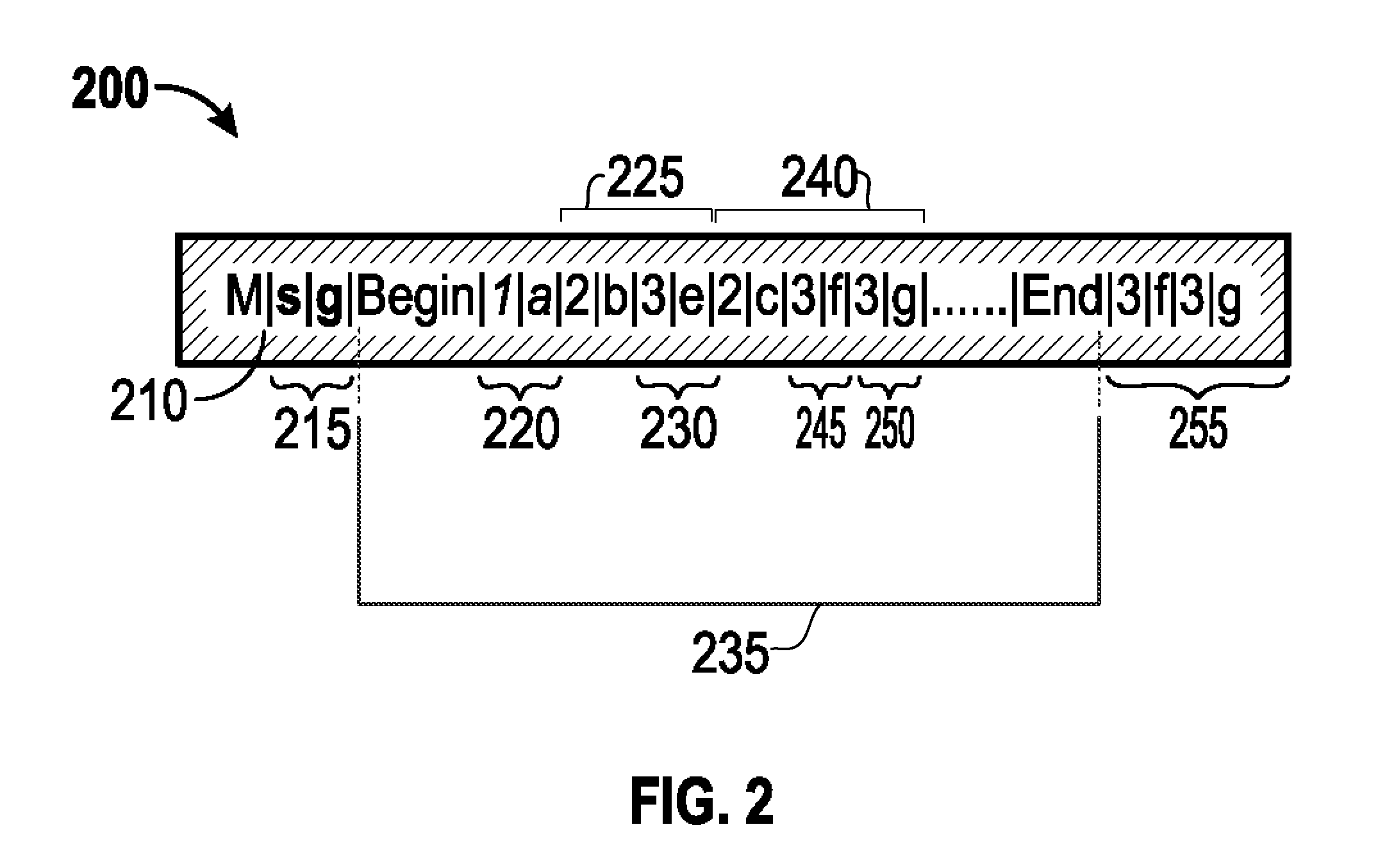
The subject technology provides configurations for receiving, at a first network device, a multicast packet of a multicast transmission from a multicast source. A header is inserted including one or more fields of information for a multicast distribution tree into the multicast packet in which the fields of information include a root level node field indicating a root node of the multicast distribution tree and one or more second level fields indicating one or more child nodes of the root node of the multicast distribution tree. In one example, the fields of information are not duplicative of routing information, stored by the first network device, corresponding to the one or more child nodes. The subject technology then forwards the multicast packet including the inserted header to respective network devices corresponding to the one or more child nodes based on the one or more fields of information from the inserted header.

Description

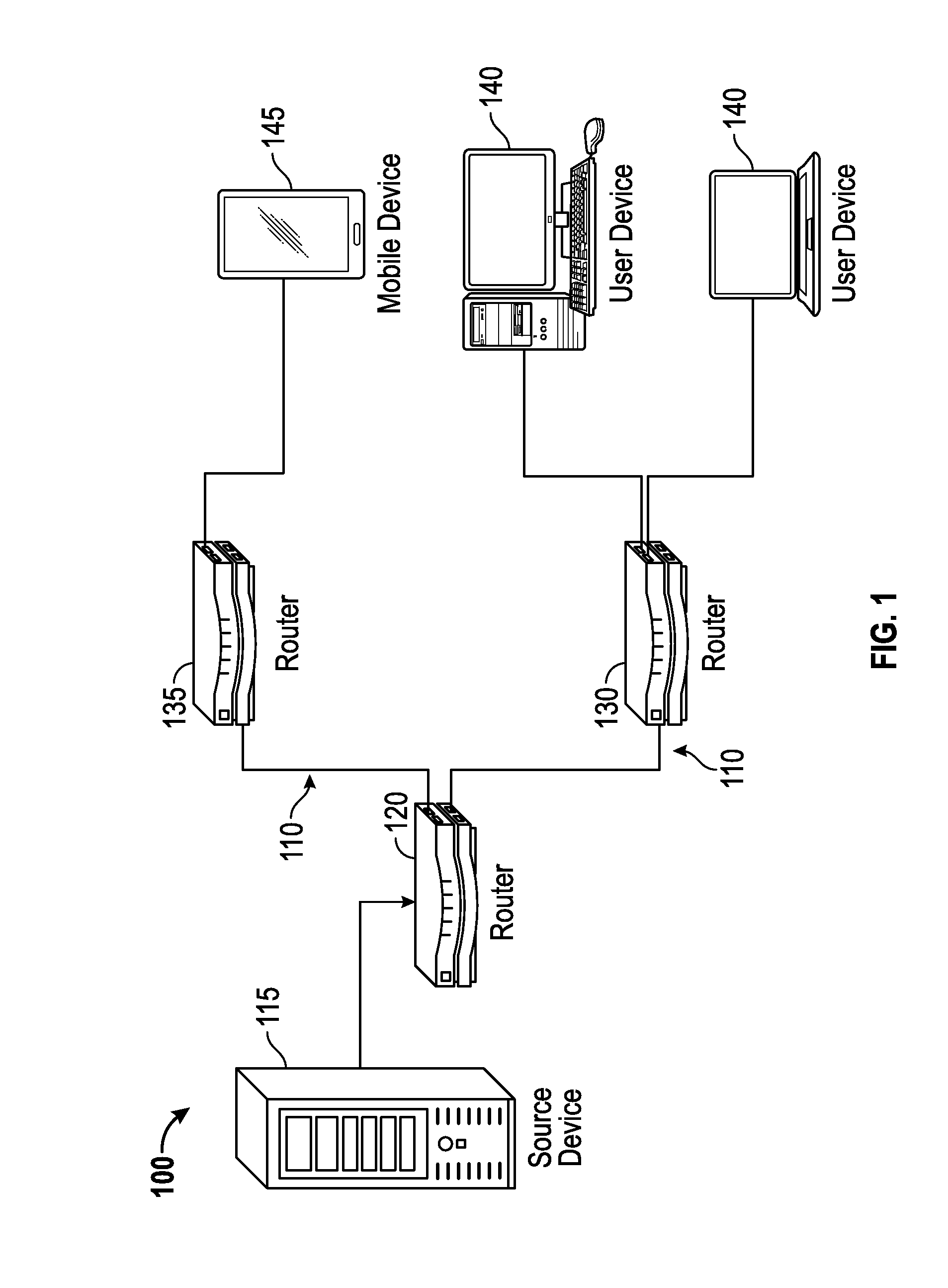
BACKGROUND[0001]This disclosure generally relates to digital communications networks, such as local or wide area networks (LANs, WANs), the Internet, etc., for distribution of information from one network location to one or more devices at other network locations.BRIEF DESCRIPTION OF THE DRAWINGS[0002]The drawing figures depict one or more implementations in accord with the present teachings, by way of example only, not by way of limitation. In the figures, like reference numerals refer to the same or similar elements.[0003]FIG. 1 illustrates an example system in which some configurations of the subject technology may be implemented.[0004]FIG. 2 conceptually illustrates an example header for including multicast state information in a given data packet of a multicast transmission.[0005]FIG. 3 conceptually illustrates signaling in a multicast network to build a multicast distribution tree according to some configurations of the subject technology.[0006]FIG. 4 conceptually illustrates ...

Claims


Application Information

Patent Timeline
IPC IPC(8): H04L12/18H04L12/753H04L12/741H04L45/16H04L45/74
CPCH04L12/1886H04L45/74H04L45/48H04L12/1863H04L45/16H04L2212/00
Inventor XU, FENGMAN
Owner VERIZON PATENT & LICENSING INC
Learn More