
Malleable Surgical Assistance Devices

a surgical assistance and device technology, applied in the field of surgical assistance devices, can solve the problems of cumbersome positioning and repositioning, high cost, and complicated system, and achieve the effect of facilitating the support of surgical assistance devices and the use of individual devices

Inactive Publication Date: 2015-02-12
EDWARDS NORTON
View PDF4 Cites 7 Cited by
  • Summary
  • Abstract
  • Description
  • Claims
  • Application Information

AI Technical Summary

Benefits of technology

The present invention is an array of surgical assistance devices that can be used to provide a light source, collect video or photo imaging, and evacuate smoke / vapor from the surgery. The devices consist of flexible tubing or light wave guides that can be connected to standard operating room equipment and a moveable base that can be positioned near the patient or surgical site. The base has a clip to hold the tubing or wave guide and may also have a weighted material to support the device. From the base, there is a bendable section of tubing or wave guide that extends towards the surgical site with a light output, imaging lens, or evacuation flute. Other components of the system help the surgeon use the devices for both the active surgery and record keeping.

Problems solved by technology

Most all of these systems, however, are extremely complex, costly, and frequently include components that must be disposed of after use.
The complexity of such systems generally contributes to their difficulty of use, being cumbersome to position and re-position as required.
Most such systems rely on large, bulky, and cumbersome brackets and frames to position devices near the surgical site without interfering with the access of the surgeon to the operation.
Lights, video equipment, and evacuation devices are currently configured on articulating arms and the like that extend over and down to the operating table (from ceiling, wall, or floor mounted brackets) in a manner that is difficult for the surgeon to manipulate.
Most such systems additionally involve terminal structures that, due to their complexity, cannot be easily sanitized and reused.

Method used


Image

  • Malleable Surgical Assistance Devices
  • Malleable Surgical Assistance Devices
  • Malleable Surgical Assistance Devices

Examples


Embodiment Construction

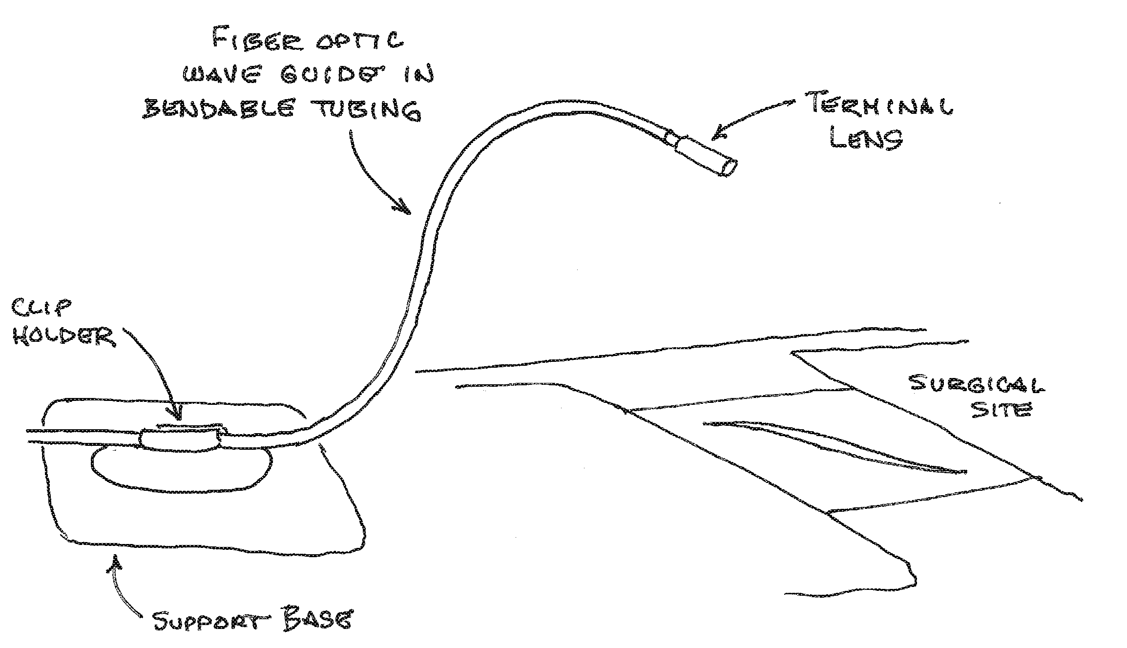
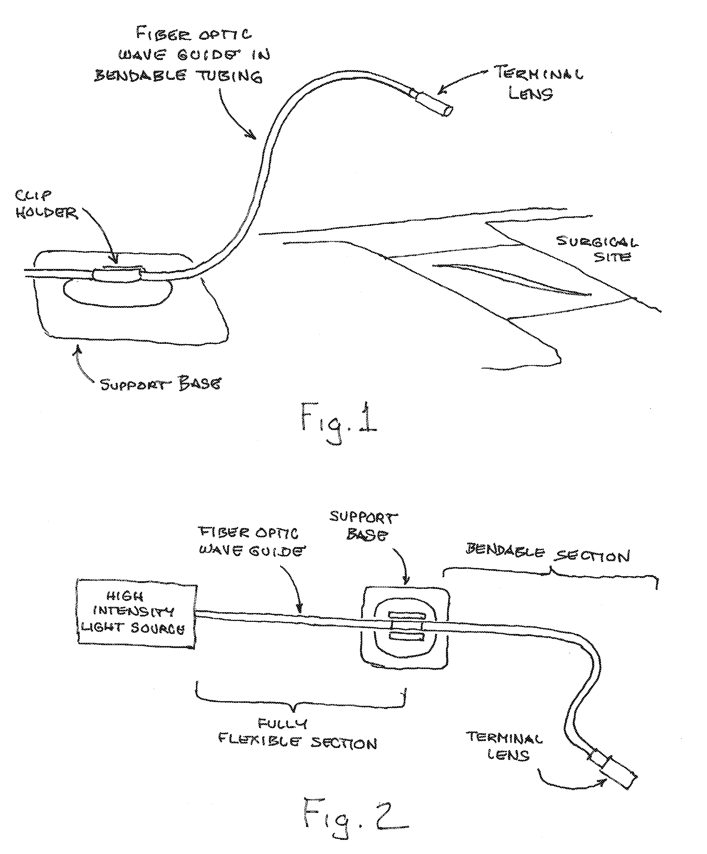
[0023]FIG. 1 shows the basic components of the system of the present invention (each of the various devices described) including a support base incorporating a clip holder structured to receive and hold a section of tubing or wave guide. The important part of the tubing or wave guide (fiber optic wave guide in the case of the light device shown in FIG. 1) is the malleable or bendable section that extends from the support base to a terminal point positioned over or near the surgical site. In the case of the light source, this terminal end comprises an output lens that may columnate or spread the light as needed. Alternate embodiments of the invention may include a lens structure on the terminal of the malleable wave guide that allows the surgeon to adjust the focus of the light source so as to spread the light or focus it in a beam.

[0024]FIG. 2 shows the various sections of the fiber optic wave guide as it extends from a high intensity light source such as is typically used in operat...


PUM


Abstract

An array of surgical assistance devices that may be used to provide a source of light to the surgical site; collect video or photo imaging of the surgical site; and / or provide smoke / vapor evacuation from the surgical site. The primary elements of the invention include lengths of flexible or malleable tubing or light wave guides that, through a first flexible section, may be connected to standard operating room equipment, through to a moveable base that may be positioned by the surgeon or the surgery personnel. The moveable base includes a clip structure designed to receive the tubing or wave guide conduit, and to be placed on or near the patient at or near the surgical site. The base may be provided with a moderately weighted material to facilitate the support of the surgical assistance device or may comprise a bendable ribbon or band with a securing clip. Extending from the moveable base is a malleable or bendable section of the tubing or wave guide that extends toward the surgical site to a terminal point configured with an appropriate light output, imaging lens, or evacuation flute. Additional components within the overall system facilitate the use of the devices by the surgeon for both the active surgical process and as a record keeping function of the same.

Description

CROSS REFERENCES TO RELATED APPLICATIONS[0001]This application claims the benefit under Title 35 United States Code §119(e) of U.S. Provisional Application 61 / 824,325, filed May 16, 2013, the full disclosure of which is incorporated herein by reference.BACKGROUND OF THE INVENTION[0002]1. Field of the Invention[0003]The present invention relates generally to devices used in surgical operating room environments to facilitate the surgical process. The present invention relates more specifically to an array of surgical assistance devices comprising malleable (bendable) conduits and tubes used for surgical site illumination, imaging of the surgical site, and evacuation of smoke and vapor from the surgical site.[0004]2. Description of the Related Art[0005]Various complex systems are presently available to provide illumination of a surgical site, video imaging of a surgical site, and smoke or vapor evacuation from a surgical site. Most all of these systems, however, are extremely complex, ...

Claims


Application Information

Patent Timeline
IPC IPC(8): A61B1/00A61B1/015A61B1/005
CPCA61B1/00147A61B1/015A61B1/005A61B1/00096A61B2017/00946A61B2217/005A61B90/30A61B2090/306A61B2090/309A61B2090/3614
Inventor EDWARDS, NORTON
Owner EDWARDS NORTON
Learn More