Method for decoupling a power take-off of a motor vehicle transmission while driving a motor vehicle

a technology of motor vehicles and transmissions, applied in mechanical devices, instruments, transportation and packaging, etc., to achieve the effect of reducing the comfort of the vehicle driver

Active Publication Date: 2015-02-05
ZF FRIEDRICHSHAFEN AG
View PDF6 Cites 3 Cited by
  • Summary
  • Abstract
  • Description
  • Claims
  • Application Information

AI Technical Summary

Benefits of technology

The invention relieves the drive train of a vehicle by using a combination of measures to disengage the form-locking shift element of the power take-off drive. This allows for reliable disengagement of the shift element when switching from traction mode to thrust mode. The invention also includes a control system that interruptions the control of the shift element can reduce wear of the operating device and a compensation method to reduce the drag torque of the motor vehicle and the auxiliary assembly. The invention also provides a maximum shift force for the shift element and a method to regulate the slip mode of the separating clutch. The invention ensures a torque-free or virtually torque-free drive train in the region of the shift element to be disengaged.

Problems solved by technology

Although coupling of a non-stationary power take-off drive can be implemented during travel of the particular motor vehicle, decoupling thereof is usually possible only when the vehicle is at a standstill, since the torque-loaded, form-locking shift element is difficult to disengage in a traction mode or even a thrust mode of the motor vehicle.
This is permitted during travel of the particular motor vehicle only in exceptional cases, however, such as in the case of serious transmission errors, for example.

Method used


Image

  • Method for decoupling a power take-off of a motor vehicle transmission while driving a motor vehicle
  • Method for decoupling a power take-off of a motor vehicle transmission while driving a motor vehicle
  • Method for decoupling a power take-off of a motor vehicle transmission while driving a motor vehicle

Examples


Embodiment Construction

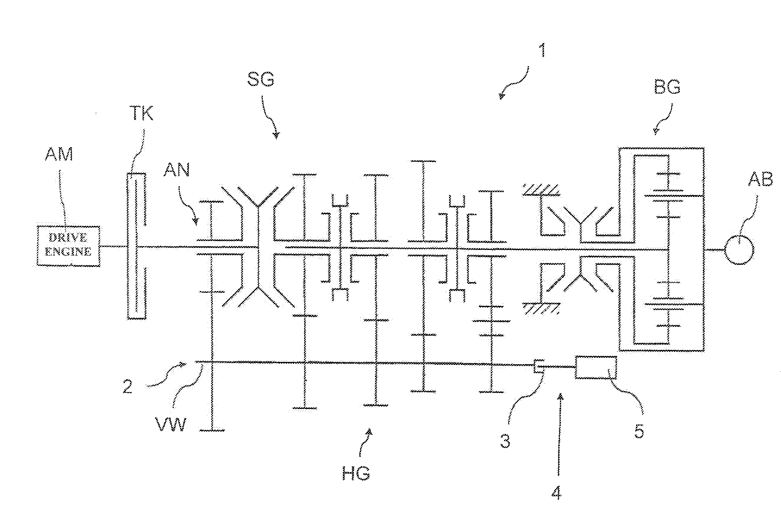
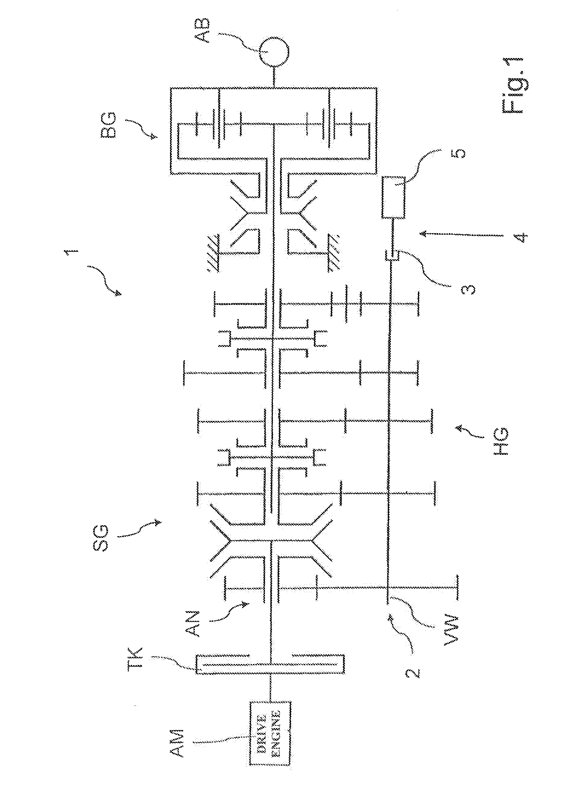
[0030]FIG. 1 shows a schematic view of a part of a drive train of a commercial vehicle according to a preferred embodiment of the invention. In this drive train, a drive engine AM in the form of an internal combustion engine can be connected on the output side, via an intermediate separating clutch TK, to a drive side AN of a motor vehicle transmission 1. The motor vehicle transmission 1 is designed as a group type automatic transmission and comprises an unsynchronized main group HG, a synchronized splitter group SG upstream of the main group HG, and a synchronized range group BG downstream of the main group HG. The range group BG is of planetary design, while the splitter group SG and the main group HG are formed by individual spur-gear stages, which, in the case of the main group HG, can each be incorporated into a power flow via unsynchronized claw clutches, and in the case of the splitter group SG, can each be incorporated into a power flow via locking synchronization and can th...


PUM


Abstract

A method of decoupling a power take-off drive of a motor vehicle transmission during travel of a motor vehicle in which a form-locking shift element of the power take-off drive is controlled for disengaging the power take-off drive. To implement reliable decoupling without interrupting travel of the motor vehicle, if disengagement of the shift element initially did not occur, control of the shift element is immediately implemented the next time a separating clutch, placed between the motor vehicle transmission and a drive engine of the motor vehicle, is actuated and / or a connection of the shift element toward an output side of the motor vehicle transmission is interrupted, over the course of a subsequent gear shift in the motor vehicle transmission. A drive train of a motor vehicle, a computer program product, and a data carrier having the computer program product.

Description

[0001]This application claims priority from German patent application serial no. 10 2013 215 249.3 filed Aug. 2, 2013.FIELD OF THE INVENTION[0002]The invention relates to a method for decoupling a power take-off drive of a motor vehicle transmission during travel of a motor vehicle, wherein a form-locking shift element of the power take-off drive is controlled and thereby disengaged. The invention also relates to a drive train of a motor vehicle, a computer program product, and a data carrier comprising the computer program product.[0003]BACKGROUND OF THE INVENTION[0004]Transmissions of commercial vehicles, in particular, often comprise power take-off drives, by means of which auxiliary assemblies of the particular commercial vehicle can be engaged at an auxiliary output of the particular transmission and operated. During operation of these auxiliary assemblies, which can be present in the form of hydraulic pumps, cutter bar mowers, refuse compactors, etc., for example, depending on...

Claims


Application Information

Patent Timeline
Patent Type & Authority Applications(United States)
IPC IPC(8): B60K25/06
CPCB60K25/06F16H61/12F16H63/44F16H63/46B60K17/28F16H2061/1248B60Y2300/423
Inventor SAUTER, INGOHAFEN, THOMASMORO-OLIVEROS, MELCHOR
Owner ZF FRIEDRICHSHAFEN AG
Why Eureka
Try Eureka