Apparatus and method for stimulator on-skin short detection

a technology of stimulator and skin, applied in the field of stimulator peripheral nerve, can solve the problems of dm-associated morbidity and mortality, low blood glucose level, pain and disability of dpn

Active Publication Date: 2015-02-05
NEUROMETRIX
View PDF8 Cites 4 Cited by
  • Summary
  • Abstract
  • Description
  • Claims
  • Application Information

AI Technical Summary

Benefits of technology

The present invention solves the problem of reporting inaccurate nerve conduction parameters by detecting a short or shunt condition during nerve conduction study testing. This is done by monitoring stimulator probe shorts through the analysis of stimulus artifact waveform and voltage difference between the anode and cathode probes. A device is provided that includes a housing, stimulation means, biosensor, acquisition means, detection means, processing means, and display means for measuring sural nerve conduction velocity and amplitude. The device is designed to be placed on a patient's anatomy for efficient and accurate testing.

Problems solved by technology

Although acutely high or low blood glucose levels are dangerous, the primary sources of DM-associated morbidity and mortality are the long term macrovascular and microvascular complications of the disease.
DPN leads to pain and disability, and is the primary trigger for foot ulcers which may result in lower extremity amputations.
Unfortunately, detection of DPN is challenging, particularly at its early stages when it may be most susceptible to intervention.
While all of these methods have utility, they are subjective, have inadequate sensitivity or specificity, or both, and have poor reproducibility.
Despite its technical and clinical attributes, nerve conduction testing is not currently widely used in the detection and monitoring of DPN.
The reasons for this include the limited availability, complexity and high cost of the study when performed by specialists, usually a neurologist, using traditional electrodiagnostic equipment.
These prior art solutions suffer from a number of deficiencies.
As a result, only limited customization is possible and the onus remains on the user of the general purpose device to address the sources of variations—such as through the placement of individual electrodes or even pre-configured electrode arrays.
As a result, despite simplifying nerve conduction measurements relative to the traditional approaches, the general purpose testing devices still require a fair amount of training in order to properly perform the nerve conduction test procedures.
Therefore devices specifically designed for testing of the median nerve cannot be used to test the sural nerve.
Another issue with general purpose testing devices is that they require two discrete components—a device with the electronic circuits needed to perform a nerve conduction test, and a nerve-specific electrode array which provides an interface between the unique characteristics of the particular nerve being tested and the common testing device.
This two-component requirement limits attempts to reduce test costs, particularly because it restricts the ability to reduce the size of the electrode array, which is a primary cost driver in nerve conduction testing.
One potential deficiency of the sural nerve conduction testing device disclosed in U.S. patent application Ser. No. 13 / 235,258 is that stimulator probes on the skin can be shorted or shunted during nerve conduction testing when gel on the skin creates an alternative conductive path between the two probes.
For example, shorting or shunting between the anode and the cathode stimulator probes of the device can be caused by an inexperienced user applying excessive amounts of conductive gels on the testing area when preparing for the sural nerve conduction test.
When gel short or shunting occurs, the alternative conductive path may cause insufficient nerve stimulation and / or inaccurate nerve conduction parameters being reported due to falsely-low recorded nerve response.

Method used


Image

  • Apparatus and method for stimulator on-skin short detection
  • Apparatus and method for stimulator on-skin short detection
  • Apparatus and method for stimulator on-skin short detection

Examples


Embodiment Construction

Device Description

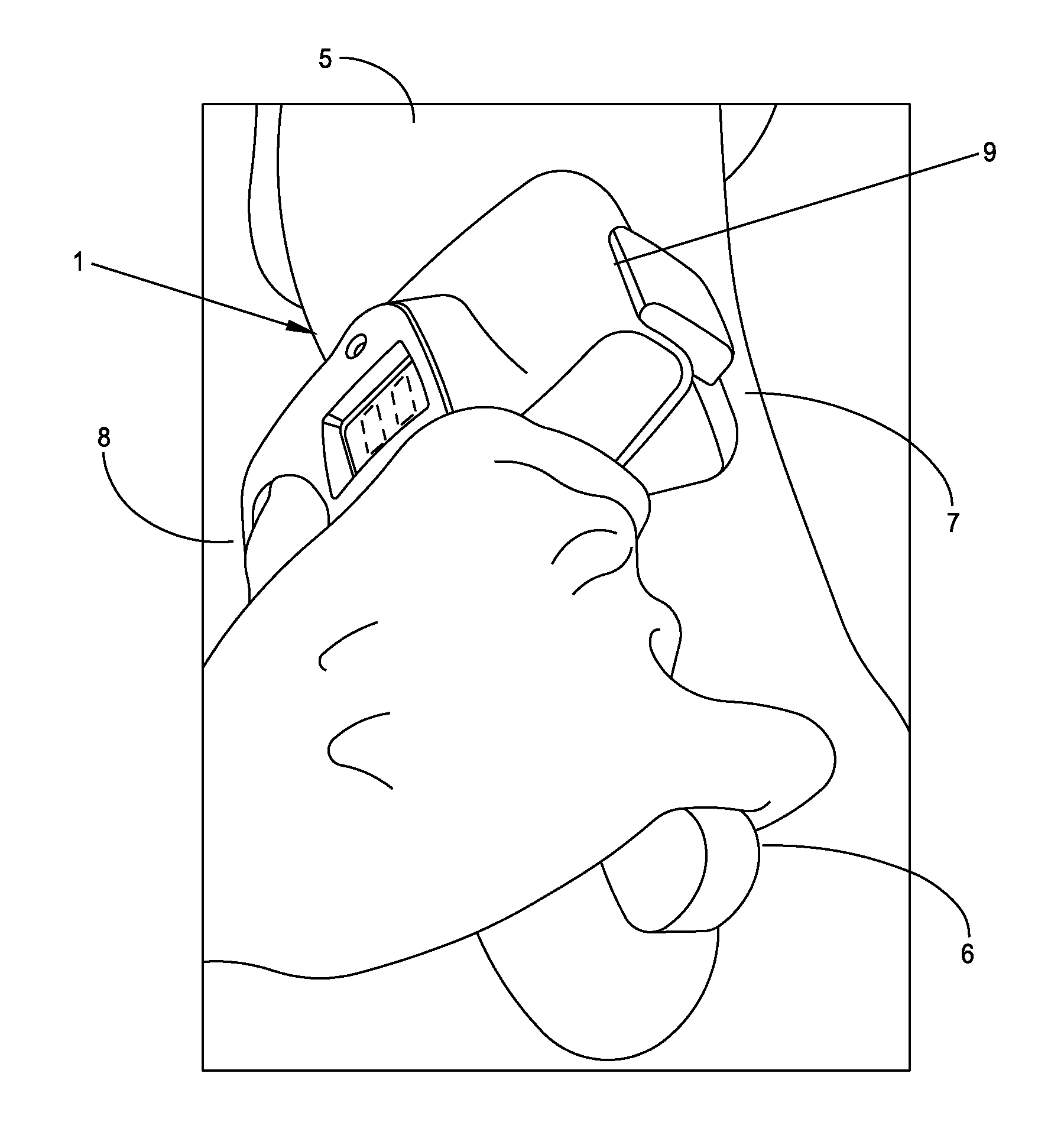
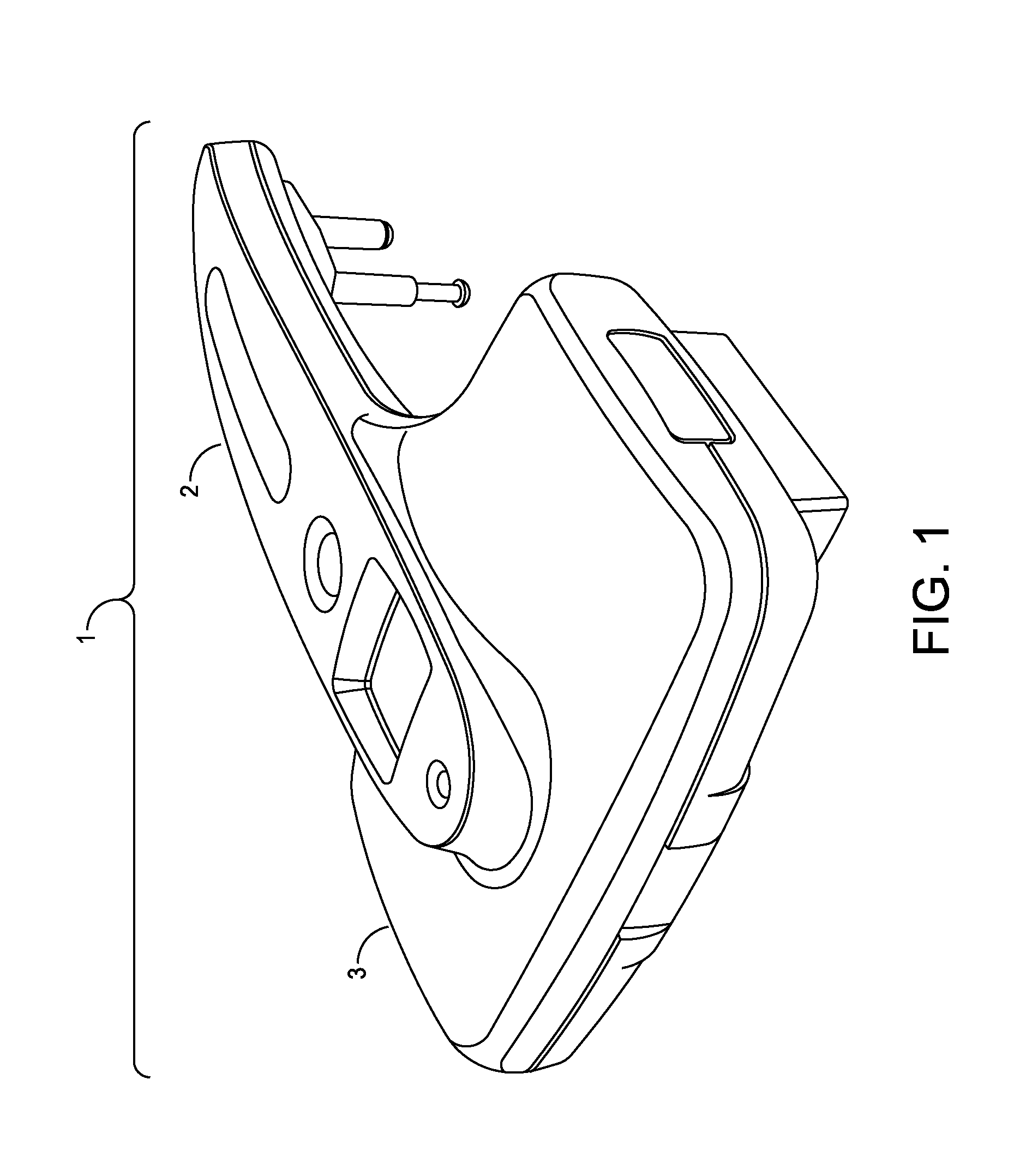
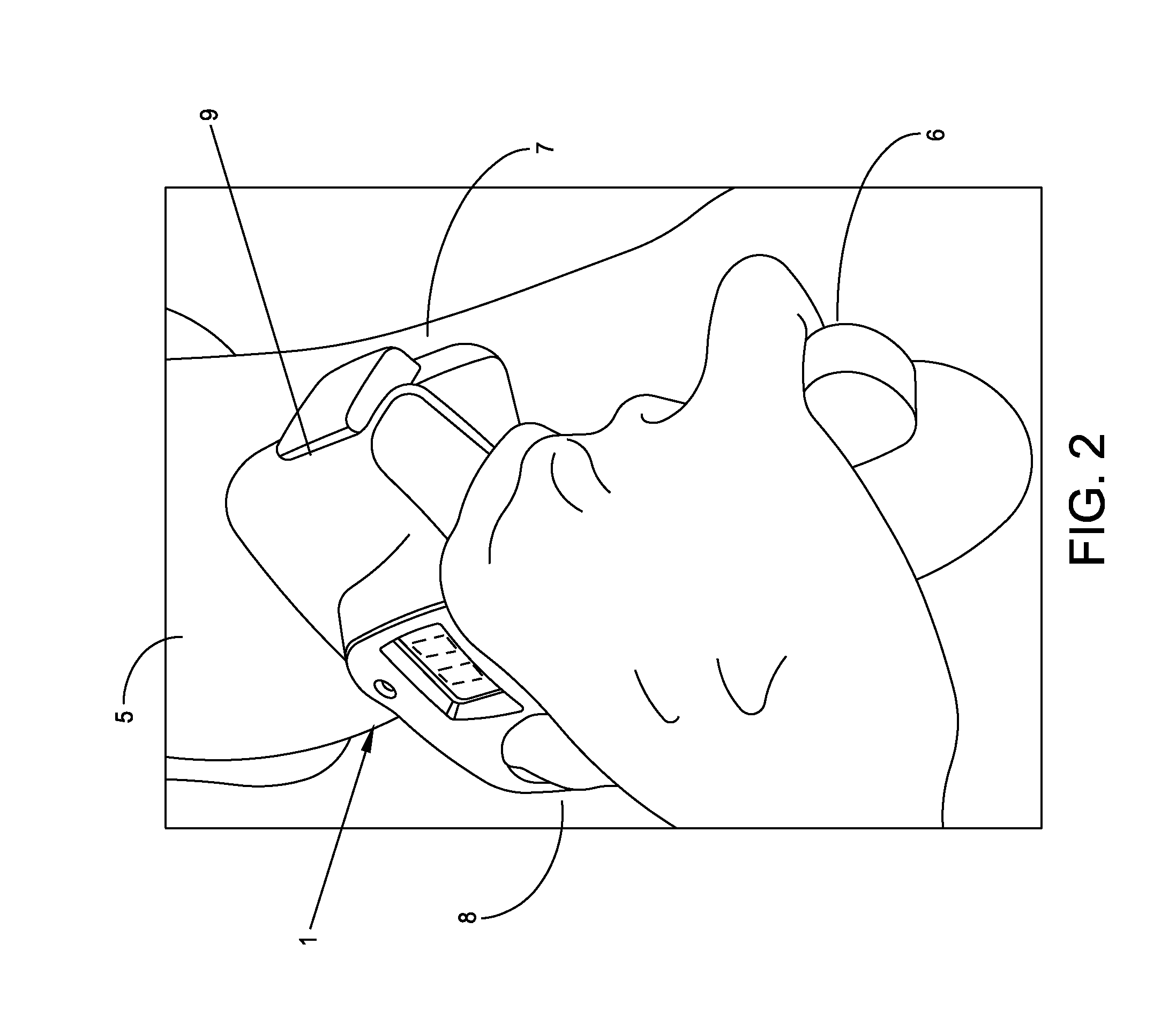
[0052]The present invention is a fully-integrated, hand-held sural nerve conduction testing device. The device is designed exclusively for non-invasive nerve conduction measurements of the human sural nerve in the region of the lower calf and ankle. The sural nerve is an almost-entirely sensory nerve formed from the merger of the medial and lateral sural cutaneous nerves which are branches of the tibial and common fibular nerves (which are themselves branches of the sciatic nerve). After forming at the distal third of the gastroc muscle, the sural nerve runs down the leg on the posterior-lateral side, then posterior to the lateral malleolus where it runs deep to the fibularis tendon sheath and reaches the lateral tuberosity of the fifth toe, where it ramifies. The sural nerve transmits sensory signals from the posterior lateral corner of the leg, the lateral foot and the 5th toe.

[0053]Sural nerve conduction is a standard and quantitative biomarker of DPN. Sural ner...


PUM


Abstract

A device for measuring sural nerve conduction velocity and amplitude, the device comprising:a housing;stimulation means mounted to the housing for electrically stimulating a human sural nerve;a biosensor releasably mounted to the housing, the biosensor comprising a plurality of electrodes for detecting a sural nerve response evoked by the stimulation means;acquisition means mounted to the housing and electrically connected to the biosensor for electrically acquiring the sural nerve response detected by the biosensor;detection means mounted to the housing and electrically connected to the stimulation means and the acquisition means for detecting shorting or shunt of the stimulation current on the surface of the skin;processing means mounted to the housing and electrically connected to the acquisition means for digitizing, processing and storing the acquired sural nerve response;calculation means mounted to the housing and electrically connected to the processing means for calculating the conduction velocity and amplitude of the processed sural nerve response; anddisplay means mounted to the housing for displaying the sural nerve conduction velocity and amplitude;wherein the stimulation means and the biosensor are designed to be placed on a patient's anatomy, in the vicinity of a sural nerve, by manipulating the housing.

Description

REFERENCE TO PENDING PRIOR PATENT APPLICATIONS[0001]This patent application:[0002](i) is a continuation-in-part of pending prior U.S. patent application Ser. No. 13 / 235,258, filed Sep. 16, 2011 by Bonniejean Boettcher et al. for APPARATUS AND METHOD FOR THE AUTOMATED MEASUREMENT OF SURAL NERVE CONDUCTION VELOCITY AND AMPLITUDE (Attorney's Docket No. NEURO-5053555758), which in turn claims benefit of:[0003](a) prior U.S. Provisional Patent Application Ser. No. 61 / 403,453, filed Sep. 16, 2010 by Shai N. Gozani for NC-STAT® SL (Attorney's Docket No. NEURO-50 PROV);[0004](b) prior U.S. Provisional Patent Application Ser. No. 61 / 459,127, filed Dec. 6, 2010 by Shai N. Gozani for NC-STAT® SL (Attorney's Docket No. NEURO-53 PROV);[0005](c) prior U.S. Provisional Patent Application Ser. No. 61 / 467,857, filed Mar. 25, 2011 by Shai N. Gozani et al. for NC-STAT® SL (Attorney's Docket No. NEURO-55 PROV);[0006](d) prior U.S. Provisional Patent Application Ser. No. 61 / 516,944, filed Apr. 11, 2011 ...

Claims


Application Information

Patent Timeline
IPC IPC(8): A61B5/00A61B5/053
CPCA61B5/053A61B5/4041A61B5/01A61B5/05A61B2560/0425A61B2560/0468A61B2562/046A61B5/24A61B5/6828A61B5/388
Inventor BOETTCHER, BONNIEJEANHERB, GLENNKONG, XUAN
Owner NEUROMETRIX
Why Eureka
Try Eureka