
Axially compact electrically driven camshaft phaser

a phaser and electrical drive technology, applied in mechanical equipment, machines/engines, gearing, etc., can solve the problems of slow operation, limited phase authority of vane-type camshaft phasers, and slow operation

Inactive Publication Date: 2015-02-05
DELPHI TECH INC
View PDF6 Cites 24 Cited by
  • Summary
  • Abstract
  • Description
  • Claims
  • Application Information

AI Technical Summary

Benefits of technology

The patent describes a device called a camshaft phaser that can adjust the timing of a camshaft in an engine. The device includes a housing with a hole at one end and a gear system inside the housing. The gear system has two splines and a flexspline inside the housing. The device also has a wiggler that can rotate to change the timing between the two splines. This adjustment can improve engine performance. The device is compact and doesn't need to extend the housing to close the hole.

Problems solved by technology

While vane-type camshaft phasers are effective and relatively inexpensive, they do suffer from drawbacks such as slow operation at low engine speeds due to low oil pressure, slow operation at low engine temperatures due to high oil viscosity, increased oil pump capacity requirement for the oil pump used to lubricate the internal combustion because the same pump is used to actuate the vane-type camshaft phaser, and the total amount of phase authority provided by vane-type camshaft phasers is limited by the amount of space between adjacent vanes and lobes and may not be sufficient to provide the desired amount of phase authority.

Method used


Image

  • Axially compact electrically driven camshaft phaser
  • Axially compact electrically driven camshaft phaser
  • Axially compact electrically driven camshaft phaser

Examples


Embodiment Construction

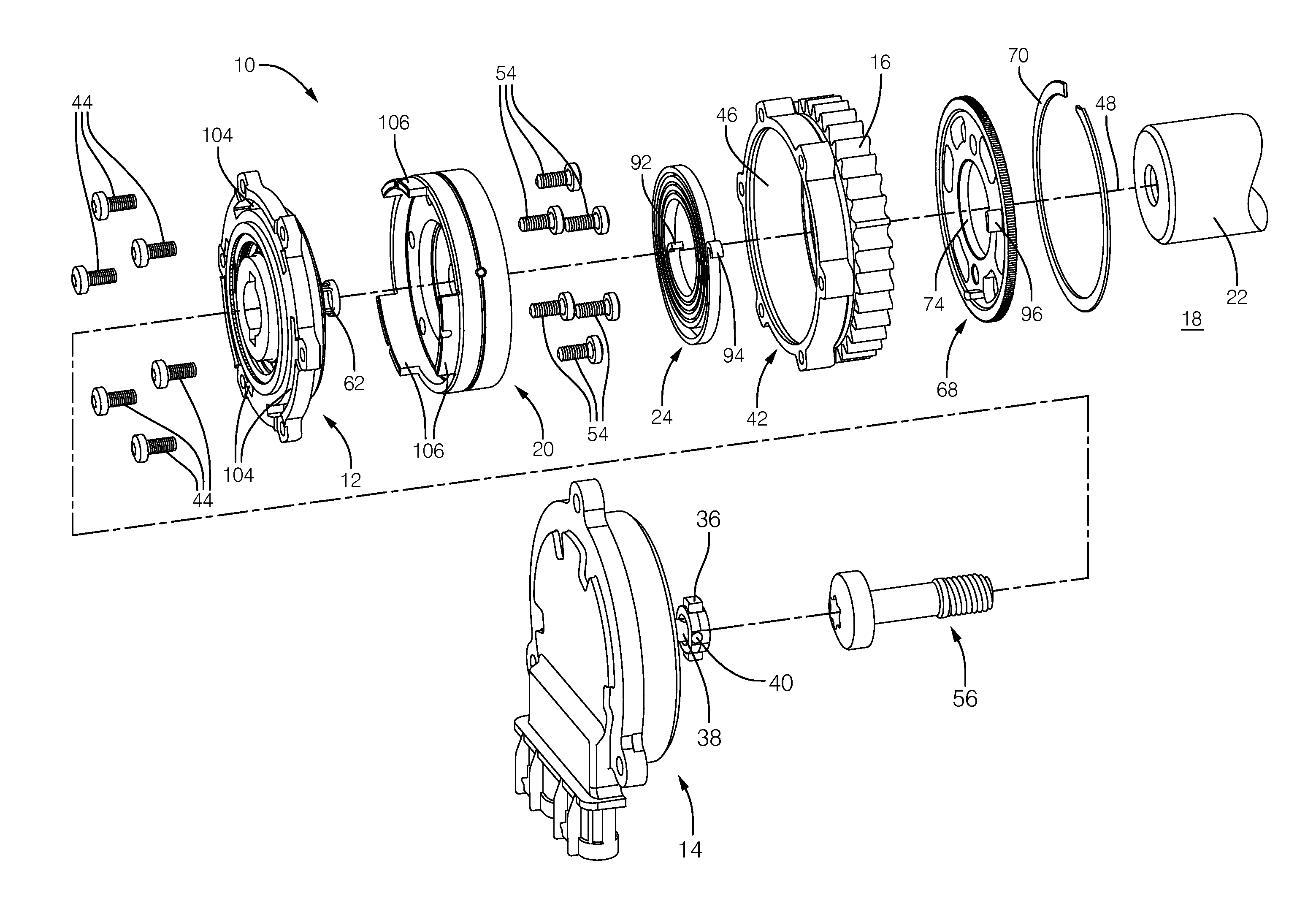
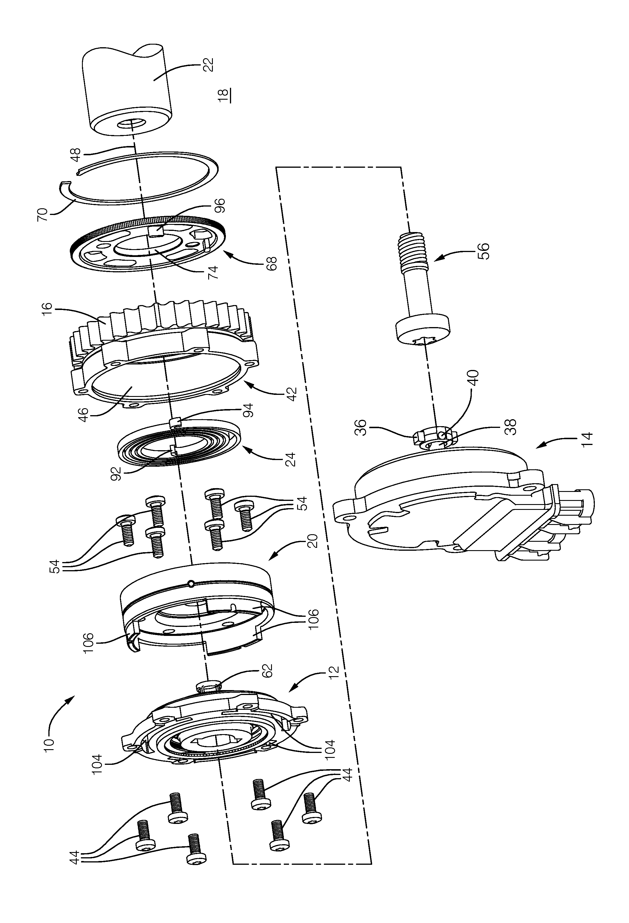
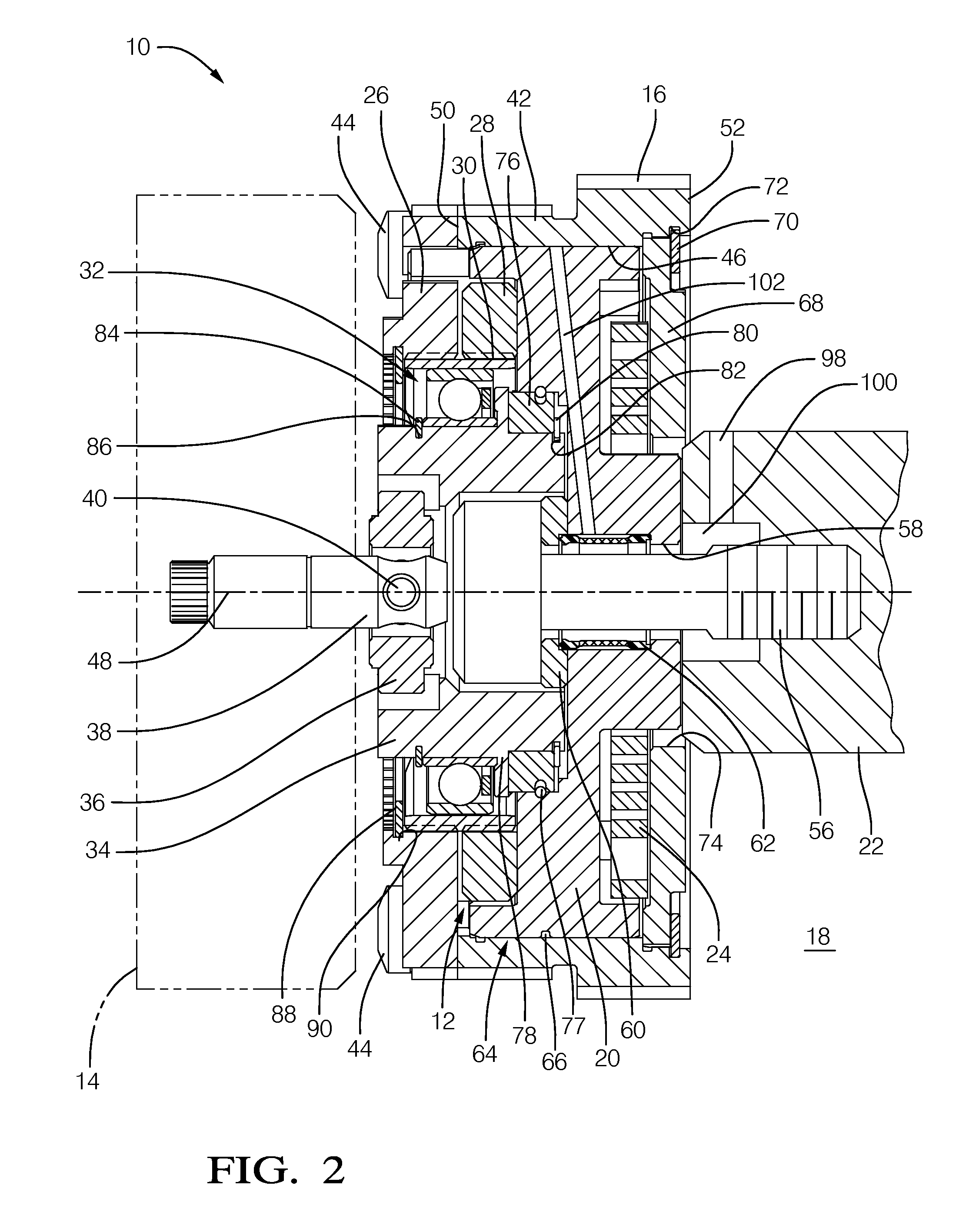
[0011]Referring to FIGS. 1 and 2, a camshaft phaser 10 in accordance with the present invention comprises a harmonic gear drive unit 12; a rotational actuator illustrated as electric motor 14 which is operationally connected to harmonic gear drive unit 12 and which may be a DC electric motor; an input sprocket 16 operationally connected to harmonic gear drive unit 12 and drivable by a crankshaft (not shown) of an internal combustion engine 18; an output hub 20 attached to harmonic gear drive unit 12 and mountable to an end of a camshaft 22 of internal combustion engine 18; and a bias spring 24 operationally disposed between output hub 20 and input sprocket 16.

[0012]Harmonic gear drive unit 12 comprises an outer first spline 26 which may be either a circular spline or a dynamic spline as described below; an outer second spline 28 which is the opposite (dynamic or circular) of outer first spline 26 and is coaxially positioned adjacent outer first spline 26; a flexspline 30 disposed ra...


PUM


Abstract

A camshaft phaser for controllably varying the phase relationship between a crankshaft and a camshaft of an internal combustion engine includes a housing having a bore with an open and extending along a longitudinal axis. The camshaft phaser also includes a harmonic gear drive unit having an outer first spline, an outer second spline which is axially adjacent to the outer first spline and disposed within the housing, a flexspline disposed radially within the outer first spline and the outer second spline, a wave generator disposed radially within the flexspline, and a rotational actuator connectable to the wave generator such that rotation of the rotational actuator causes relative rotation between the outer first spline and the outer second spline. The outer first spline is fixed to the housing in order to prevent relative rotation therebetween and serves to close the open end of the housing.

Description

TECHNICAL FIELD OF INVENTION[0001]The present invention relates to a camshaft phaser which uses an electric motor to vary the phase relationship between a crankshaft and a camshaft of an internal combustion engine; more particularly, to such a camshaft phaser which comprises a harmonic gear drive unit; and even more particularly to such a camshaft phaser which is axially compact.BACKGROUND OF INVENTION[0002]Camshaft phasers for varying the timing of combustion valves in internal combustion engines are well known. A first element, known generally as a sprocket element, is driven by a chain, belt, or gearing from the crankshaft of the internal combustion engine. A second element, known generally as a camshaft plate, is mounted to the end of a camshaft of the internal combustion engine. A common type of camshaft phaser used by motor vehicle manufactures is known as a vane-type camshaft phaser. U.S. Pat. No. 7,421,989 shows a typical vane-type camshaft phaser which generally comprises a...

Claims


Application Information

Patent Timeline
Patent Type & Authority Applications(United States)
IPC IPC(8): F16H25/08
CPCF16H25/08F16H35/008F16H49/001F01L2001/3521F01L2820/032Y10T74/2102
Inventor KIMUS, PIERREDAVID, PASCALBOURNICHE, ERIC
Owner DELPHI TECH INC
Learn More