Exhaust gas recirculation control

Active Publication Date: 2015-02-05
FORD GLOBAL TECH LLC
View PDF9 Cites 8 Cited by
  • Summary
  • Abstract
  • Description
  • Claims
  • Application Information

AI Technical Summary

Benefits of technology

The patent text describes an exhaust gas recirculation system for engines that reduces exhaust emissions and improves fuel economy. To achieve this, the system needs to accurately control the flow of re-circulated exhaust. By using errors in exhaust back pressure and intake oxygen concentrations, the system can adapt to achieve the desired EGR flow rate and control the EGR valve to meet target EGR dilutions in the engine. This increased accuracy in EGR valve control can improve engine performance, increase fuel economy, and reduce emissions.

Problems solved by technology

For example, too much EGR flow may retard engine performance and cause a hesitation on acceleration.
On the other hand, too little EGR flow may reduce the ability to decrease heat losses to coolant by lowering temperatures of combusted gases, reduce the ability to improve knock tolerance by diluting and cooling end gases, and reduce the ability to decrease / eliminate enrichment requirements by lowering exhaust gas temperatures, for example.
For example, the inventors herein have recognized that accurate control of an electric EGR valve requires accurate exhaust backpressure estimates, but this value can have various sources of error which degrade EGR flow estimation.
For example, errors in estimating exhaust pressure differences between the output of a turbine and an EGR valve or errors in estimating a pressure drop across the EGR valve may lead to potential errors in the EGR valve position commanded by a controller.
Such estimation errors could lead to either too much or too little EGR valve lift and consequently delivery of an incorrect amount of EGR to the engine intake based on engine operating conditions.
Delivery of an incorrect amount of EGR to the engine intake may potentially cause fuel economy and tailpipe emissions degradations, e.g., due to engine misfire because of excessive EGR being delivered.
Further, errors between actual and desired intake oxygen concentrations may be used to adaptively update exhaust back pressure estimations to control the EGR valve to meet target EGR dilutions in the engine.

Method used


Image

  • Exhaust gas recirculation control
  • Exhaust gas recirculation control
  • Exhaust gas recirculation control

Examples


Embodiment Construction

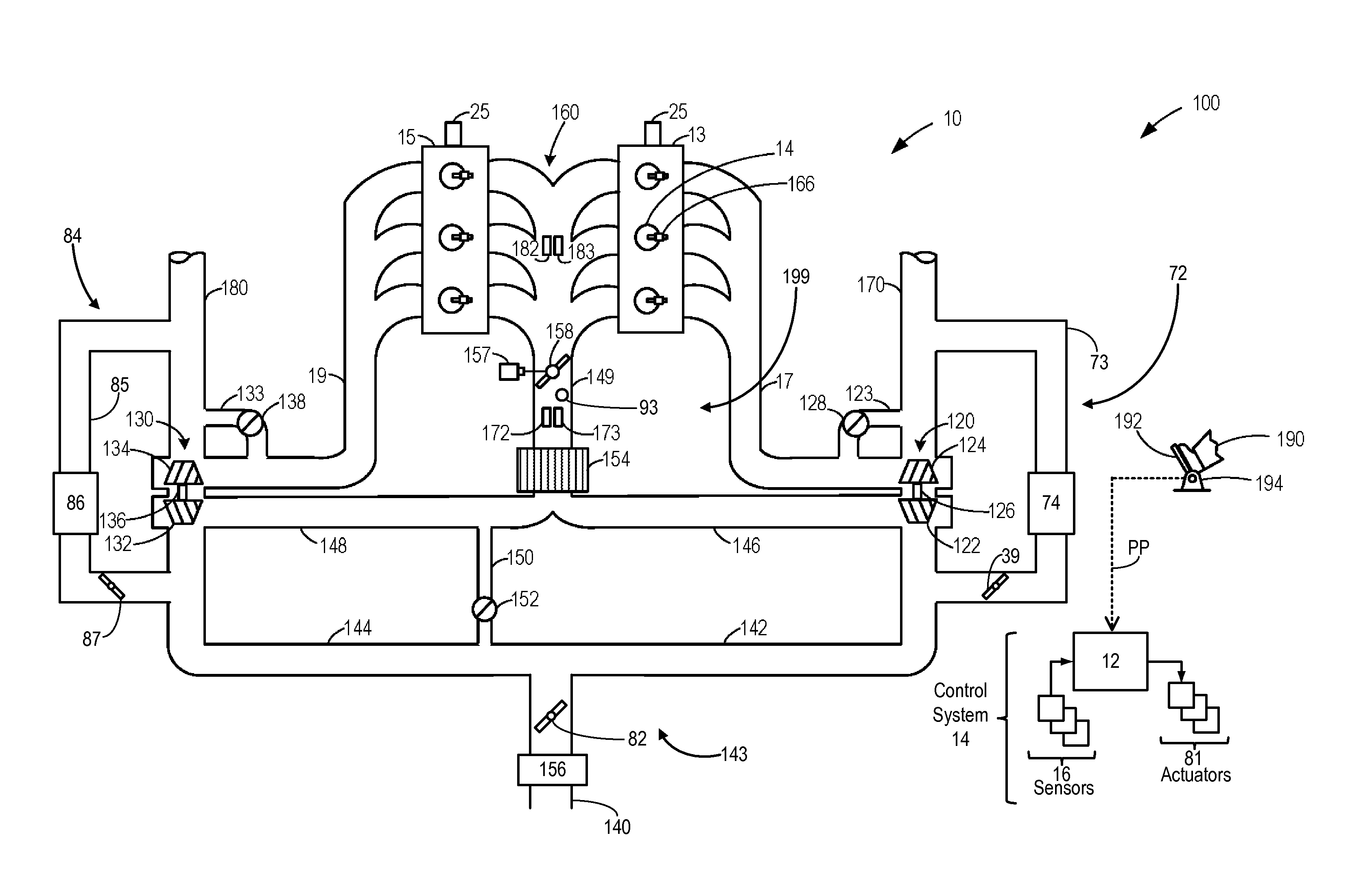
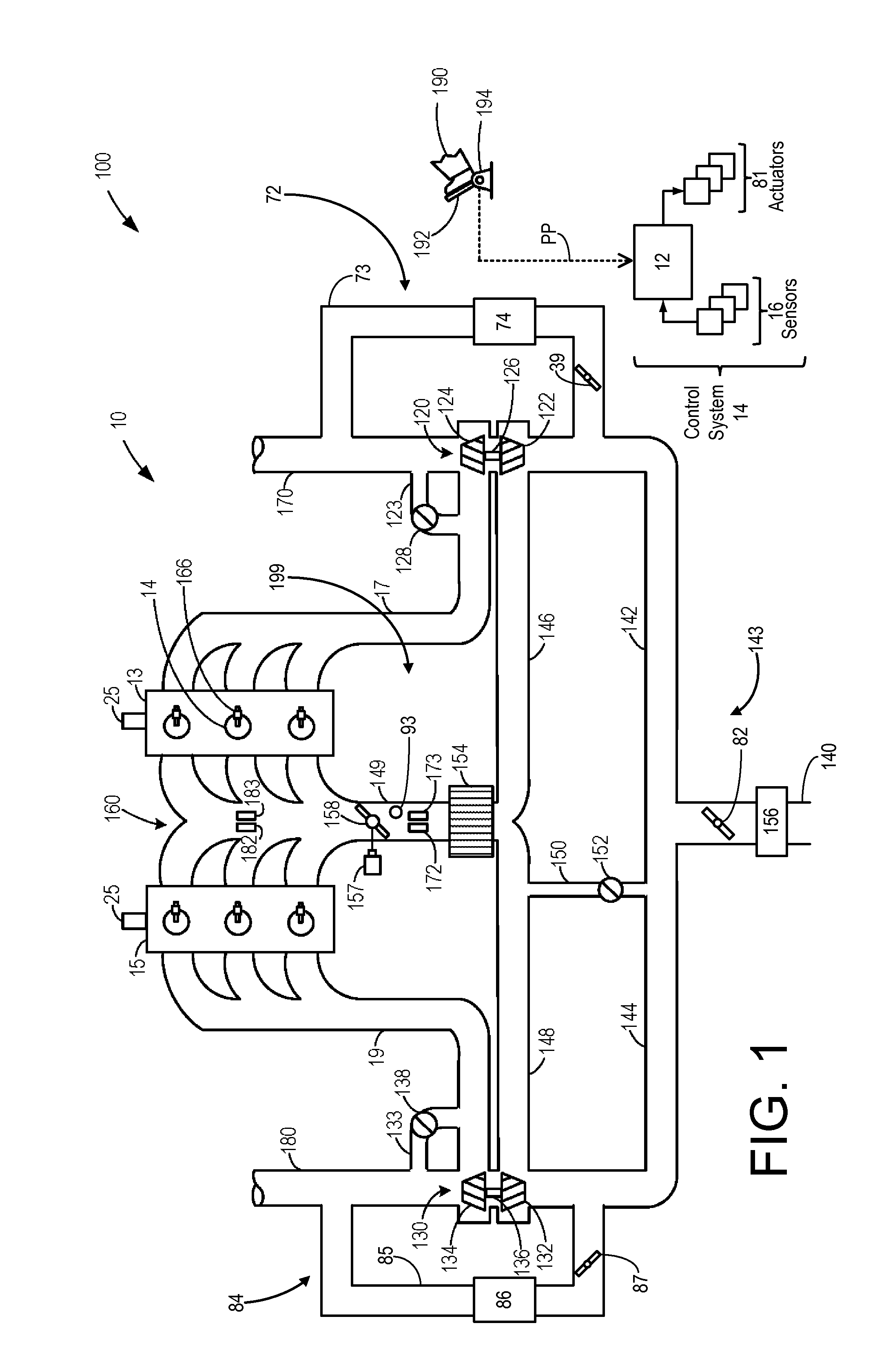
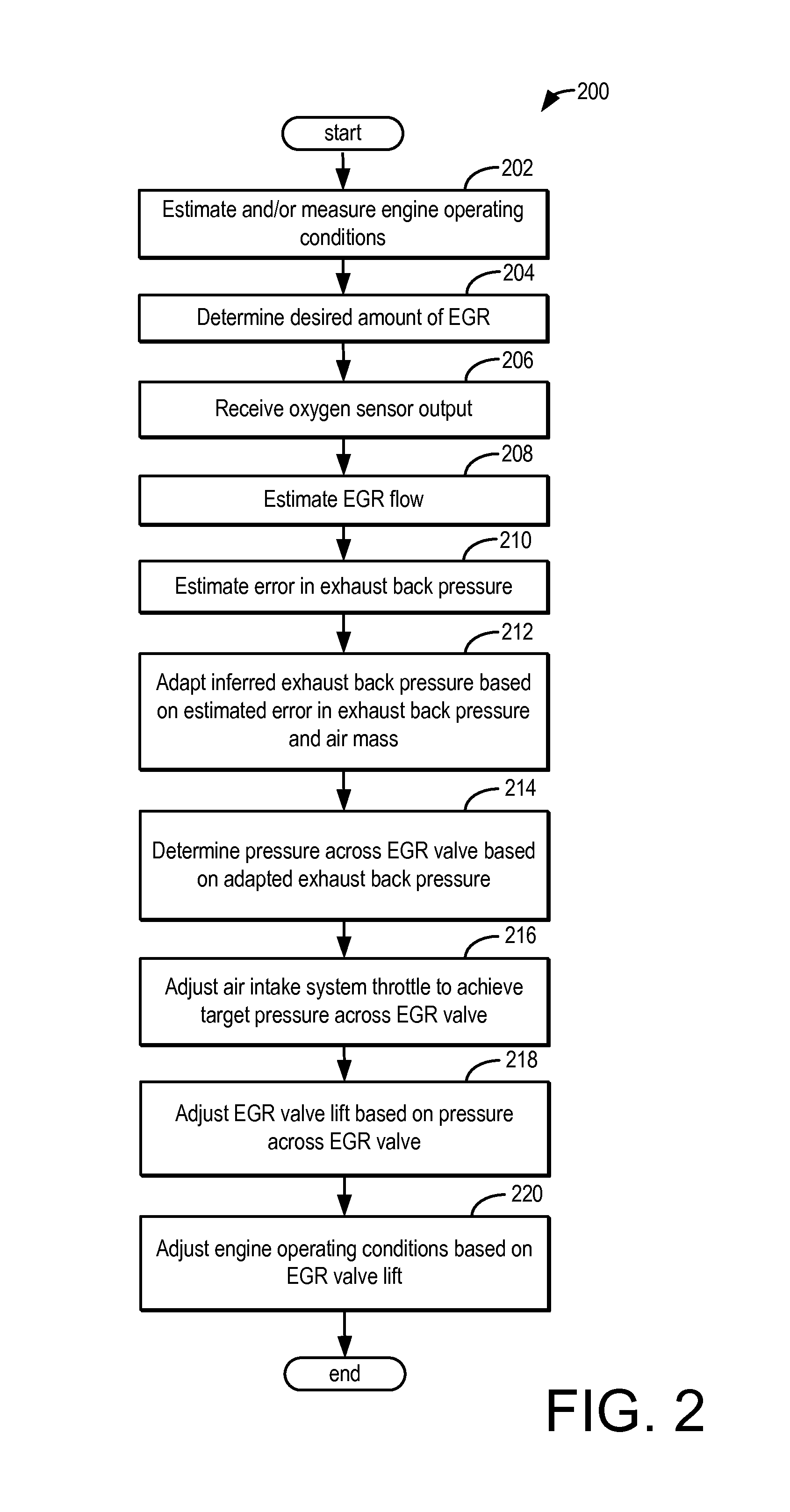
[0012]The following description relates to systems and methods for controlling an exhaust gas recirculation valve in an engine, e.g., the engine system shown in FIG. 1, by determining errors in exhaust backpressure estimates and adapting EGR flow estimations based on these errors to meet target EGR dilutions in the engine. As shown in FIGS. 2 and 3, errors in exhaust back pressure determination based on a desired EGR rate and an actual rate determined via an intake air oxygen sensor may be used to adapt pressure estimations across the EGR valve so that a target EGR flow rate may be accurately achieved. Further, errors between actual and desired intake oxygen concentrations may be used to adaptively update exhaust back pressure estimations to control the EGR valve to meet target EGR dilutions in the engine. By determining errors in exhaust backpressure estimates and adapting EGR flow estimations based on these errors, increased accuracy in EGR valve control may be achieved thereby po...


PUM


Abstract

Methods and systems are disclosed for controlling an exhaust gas recirculation valve in an engine by determining errors in exhaust backpressure estimates and adapting EGR flow estimations based on these errors to meet target EGR dilutions in the engine. In one example approach, a method comprises adjusting valve position based on desired EGR flow and estimated EGR flow, where the estimated flow is based on estimated exhaust backpressure, and the estimated exhaust backpressure is updated based on errors between actual and desired intake oxygen concentration.

Description

BACKGROUND AND SUMMARY[0001]Engine systems may be configured with exhaust gas recirculation (EGR) systems wherein at least a portion of the exhaust gas is recirculated to the engine intake. Such EGR systems my enable reduction in exhaust emissions while also increasing fuel economy.[0002]Various sensors may be included in the engine system to estimate the EGR flow and control an amount of EGR delivered to the engine intake. One example of such an EGR system is illustrated by Tonetti et al. in U.S. Pat. No. 7,267,117. Herein, an oxygen sensor is included in the engine air intake, and based on the output of the oxygen sensor, a controller is configured to adjust the position of an EGR valve to thereby provide a desired amount of EGR.[0003]EGR systems must precisely control the flow of re-circulated exhaust. For example, too much EGR flow may retard engine performance and cause a hesitation on acceleration. On the other hand, too little EGR flow may reduce the ability to decrease heat ...

Claims


Application Information

Patent Timeline
IPC IPC(8): F02D41/14F02D43/00
CPCF02D43/00F02D41/145F02D41/0072F02D41/1456F02D2041/0017F02M26/08F02M26/10F02M26/24Y02T10/40
Inventor MAKKI, IMAD HASSANCLARK, TIMOTHY JOSEPH
Owner FORD GLOBAL TECH LLC
Why Eureka
Try Eureka