
Piston and internal combustion engine therewith and method of constructing the piston

Active Publication Date: 2009-02-26
TENNECO
View PDF18 Cites 8 Cited by
  • Summary
  • Abstract
  • Description
  • Claims
  • Application Information

AI Technical Summary

Benefits of technology

[0007]A piston for an internal combustion engine manufactured in accordance with the present invention reduces carbon build-up on a top land of the piston, reduces carbon build-up in ring grooves and on piston rings with the grooves, improves the movement of the piston rings, reduces oil blow-by and consumption, reduces bore polishing typically caused by carbon build-up, reduces exhaust emissions, and overall improves the running performance of the engine.

Problems solved by technology

It is known that internal combustion engines, and particularly diesel engines, consume relatively high amounts of oil, and in the process, produce undesirable exhaust emissions.
In addition, with the oil consumption comes carbon build-up on surfaces of the piston, such as the top land area, including in the annular ring grooves.
As such, the ring movements can be restricted by the carbon build-up, thereby resulting in oil blow-by, reduced engine performance, reduced engine component life, and increased oil consumption and emission.

Method used


Image

  • Piston and internal combustion engine therewith and method of constructing the piston
  • Piston and internal combustion engine therewith and method of constructing the piston
  • Piston and internal combustion engine therewith and method of constructing the piston

Examples


Embodiment Construction

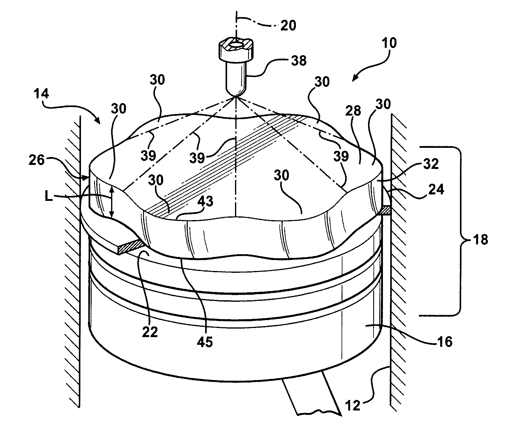
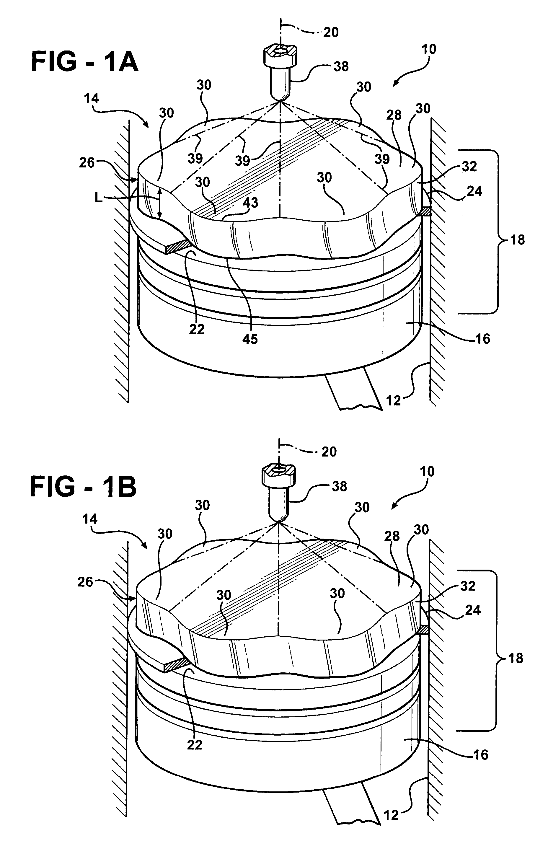
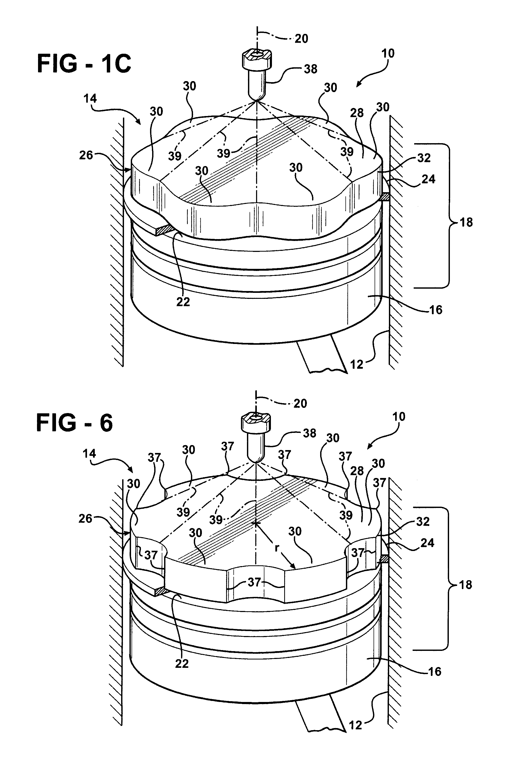
[0019]Referring in more detail to the drawings, FIGS. 1A-1C illustrate a piston 10 constructed according to one presently preferred embodiment of the invention. The piston 10 is disposed in a cylinder bore 12 of an internal combustion engine, such as a diesel engine represented generally at 14. The piston 10 has a piston body 16, either cast or forged, with a substantially cylindrical upper crown 18 extending along a central axis 20. The upper crown 20 is formed with at least one annular ring groove 22 for floating receipt of a piston ring, wherein a top upper most piston ring 24 (shown fragmented for clarity) facilitates guiding the piston 10 during reciprocation, while also acting to inhibit the passage of oil upwardly from below the piston body 16. The upper crown 18 has a top land 26 extending upwardly from the upper most ring groove 22 to a compression or top surface 28 of the piston body 16. The top land 26 has a plurality of waves 30 extending axially generally along the dire...


PUM

PropertyMeasurementUnit
Depthaaaaaaaaaa

Abstract

A piston and internal combustion engine therewith constructed in accordance with the present invention has a piston body with an upper crown having a substantially cylindrical outer surface depending from a top surface along a central axis. At least one annular ring groove extends radially into the outer surface to provide a top land extending from the ring groove to the top surface. A plurality of waves are formed circumferentially about the top land. Each of the waves has a valley extending radially into the outer surface of the top land and extending from the top surface to the ring groove. The waves traverse from the top surface to the ring groove and are configured in substantially non-overlapping relation with one another and in a predetermined orientation relative to at least one of a fuel spray stream, a pin bore axis or a thrust axis of the piston.

Description

CROSS-REFERENCE TO RELATED APPLICATION[0001]This application claims the benefit of U.S. Provisional Application Ser. No. 60 / 944,244, filed Jun. 15, 2007, which is incorporated herein by reference in its entirety.BACKGROUND OF THE INVENTION[0002]1. Technical Field[0003]This invention relates generally to internal combustion engines, and more particularly to pistons constructions therefore and arrangements therein.[0004]2. Related Art[0005]It is known that internal combustion engines, and particularly diesel engines, consume relatively high amounts of oil, and in the process, produce undesirable exhaust emissions. In addition, with the oil consumption comes carbon build-up on surfaces of the piston, such as the top land area, including in the annular ring grooves. As such, the ring movements can be restricted by the carbon build-up, thereby resulting in oil blow-by, reduced engine performance, reduced engine component life, and increased oil consumption and emission. As such, there ar...

Claims


Application Information

Patent Timeline
IPC IPC(8): F02F3/00
CPCF02B3/06F02B23/0669F02B23/0687F02B2275/14Y10T29/49249F16J15/0887Y02T10/125Y02T10/123F02F3/28Y02T10/12
Inventor TAYLOR, ANDYMARTINS, AIRTONHORN, MAGNUSFRENNFELT, CLAESDURHAM, JOHNMACKNEY, DEREKMCGROGAN, SEANTIAN, TIANWONG, VICTOR
Owner TENNECO
Learn More