
Connector system and building components for use in building construction

a technology for connecting systems and building components, applied in the direction of connecting rods, controlling members, building components, etc., can solve the problems of difficulty and cost of transportation, legal or practical size limitations may still need to be observed, and it is impossible to transport an entire house from a factory in view

Inactive Publication Date: 2015-01-29
POUSTCHI BEHROUZ
View PDF14 Cites 7 Cited by
  • Summary
  • Abstract
  • Description
  • Claims
  • Application Information

AI Technical Summary

Benefits of technology

The patent describes a connector system for joining building components together. The male connector has a tapered protrusion that fits into a receptacle in the female connector, allowing the components to be easily aligned. The tapered protrusion has a decreasing size in at least one dimension, making it easier to align the components. The system can also be used in structural panels, providing a secure connection between components. Overall, this technology improves the connection between building components and helps to create strong and stable structures.

Problems solved by technology

Even if possible, it may be impractical to transport an entire house from a factory in view of potential transportation difficulties such as physical obstacles on roadways between the site and factory (e.g. bridges, tunnels, overhead obstructions and the like).
Indeed, the potential difficulty and cost of transportation may be a deterrent for using this approach, particularly as the distance between the building site and the factory increases.
Although the pieces will be smaller than the entire house, the cost of transportation may still be a deterrent for using this approach, and legal or practical size limitations may still need to be observed.

Method used


Image

  • Connector system and building components for use in building construction
  • Connector system and building components for use in building construction
  • Connector system and building components for use in building construction

Examples


embodiment 300

[0096]FIGS. 32-35 illustrate an alternative connector system embodiment 300. FIGS. 32 and 33 illustrate a male connector 302 of system 300 and corresponding female connector 352 of system 300, respectively, both in perspective view. FIG. 34 illustrates the male and female connectors 302, 352 after having been mated. FIG. 35 illustrates the mated connectors 302 and 352 attached to respective framing members 400 and 402.

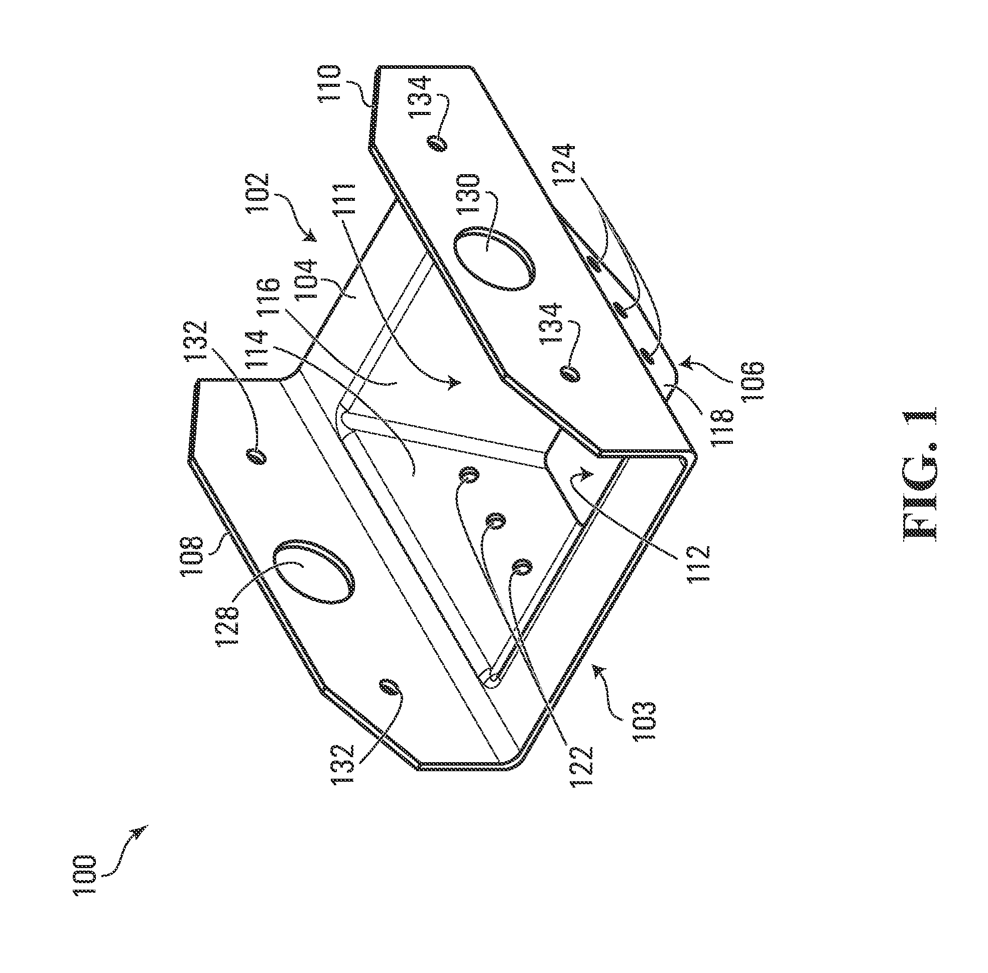
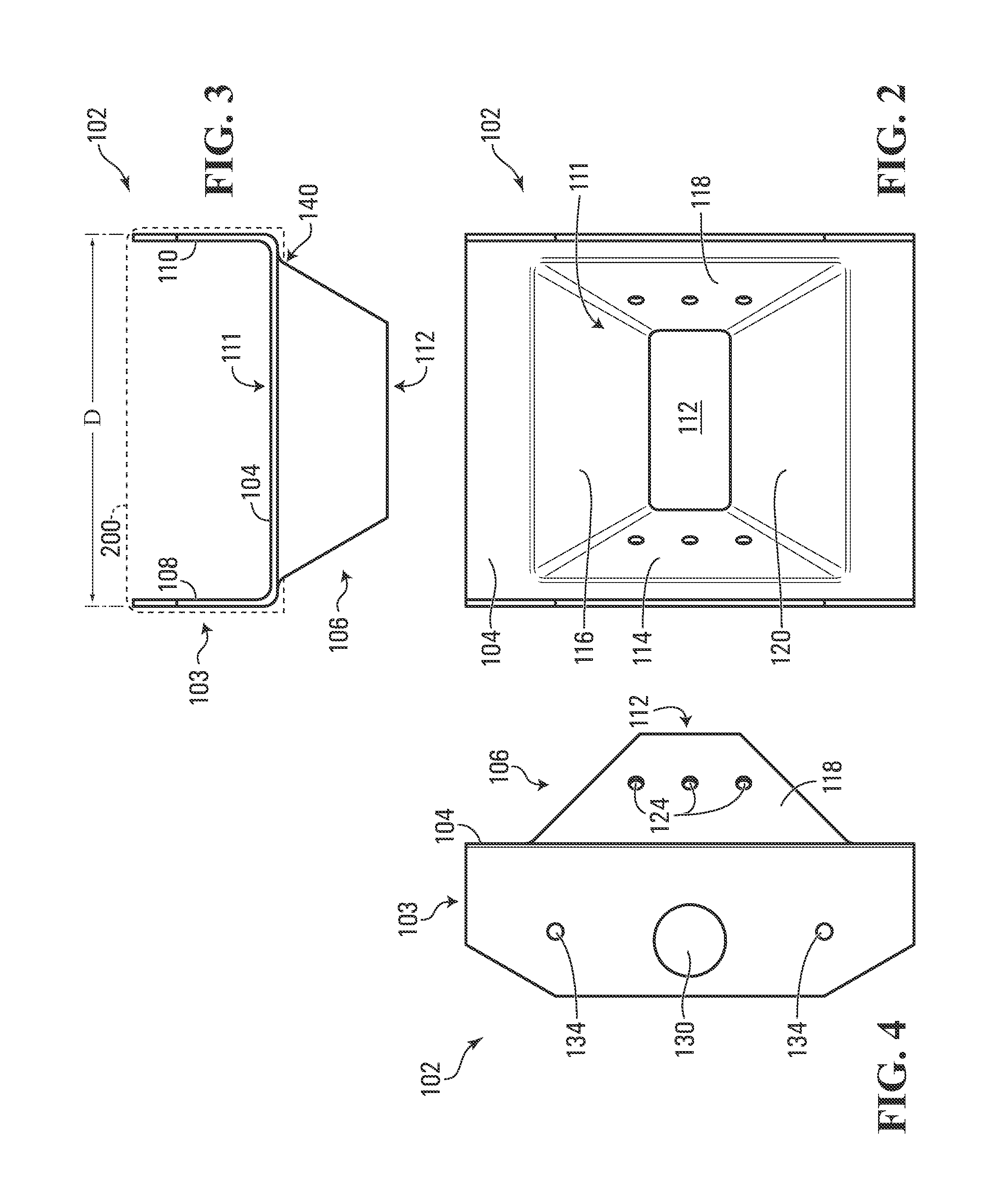
[0097]Referring FIG. 32, it can be seen that the connector body 303 of example male connector 302 is similar to that of earlier described male connector 102. That is, connector body 303 comprises a plate 304 and flanges 308 and 310 extending upwardly on opposite sides of the plate 104. As well, connector body 303 has a hollow tapered protrusion 306 protruding downwardly therefrom. However, the three-dimensional shape of the tapered protrusion 306 in this embodiment is different from that of tapered protrusion 106 of the earlier discussed embodiment. In particular, two ...

embodiment 800

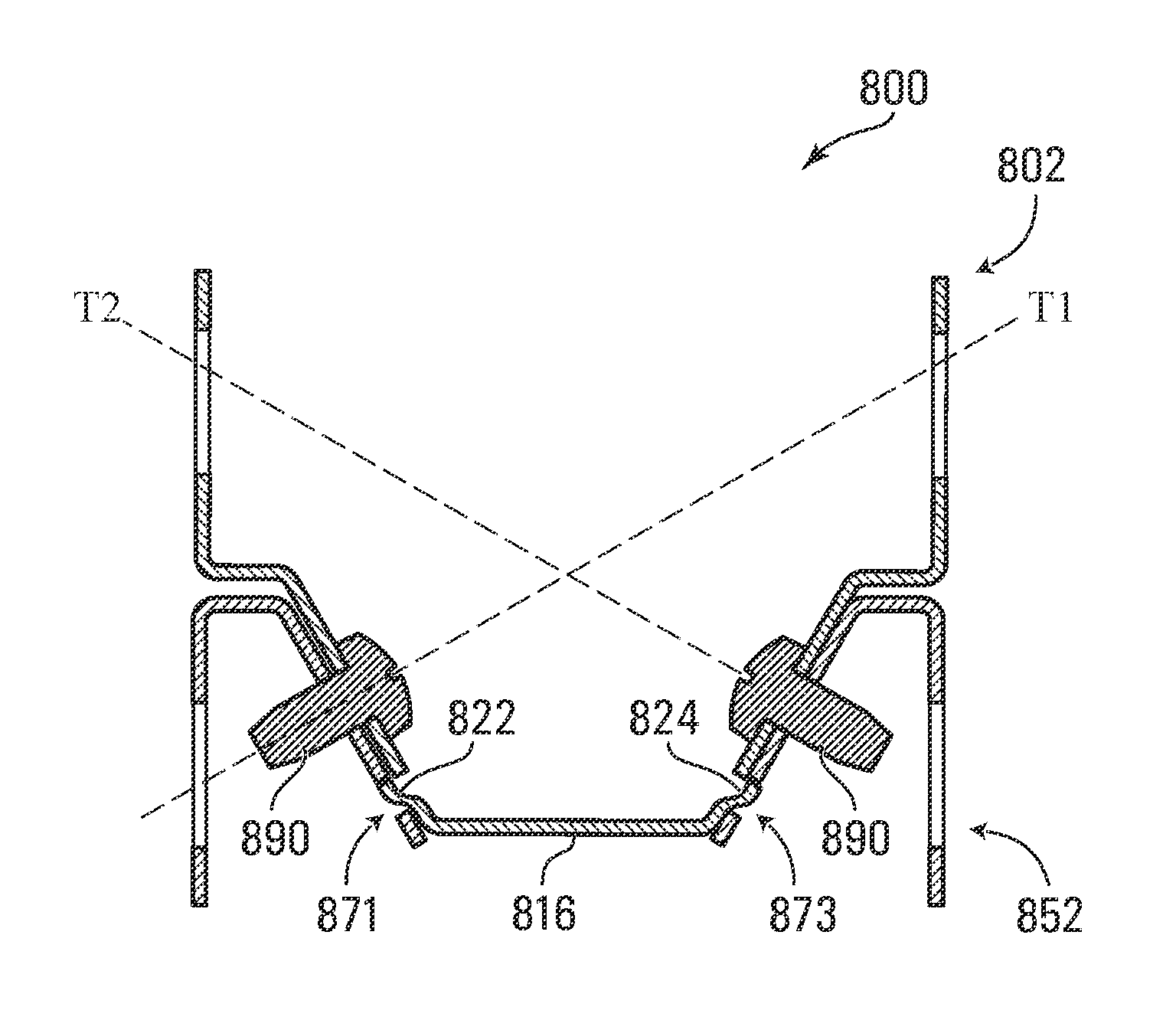
[0128]Referring to FIGS. 49-62, a further embodiment 800 of a connector system is illustrated. The connector system 800, which may be referred to as a locking or snap-fit connector system 800, includes a male connector 802 and a female connector 852. As will become apparent, this connector system 800 differs from the connector system 100 described above, primarily in that the male and female connectors collectively define a snap-fit for joining the male connector 802 with the female connector 852 upon mating of the two and in that manufacture of the male connector and / or the female connector may be simplified.

[0129]The male connector 802 is illustrated in FIGS. 49-53, in perspective view, plan view, front view, side view and cross sectional view, respectively. The male connector 802 may be formed from a single piece of sheet metal (e.g. progressive stamped sheet metal) or another rigid material.

[0130]The exemplary male connector 802 comprises a connector body 803 and a tapered protr...


PUM


Abstract

An example connector system embodiment may be used to quickly align and interconnect two framing members, planar panels or other building components, e.g. during erection of prefabricated or component housing. The connector system includes a male connector and a female connector. The connectors can be attached to, or may be integrally formed with, respective building components to be interconnected. The male connector comprises a tapered protrusion having a cross-sectional extent that decreases monotonically, in at least one dimension, in the direction of protrusion, so as to impart a taper to the tapered protrusion in the at least one dimension. A corresponding female connector comprises a receptacle for receiving the tapered protrusion. The taper may facilitate centering of the male connector with respect to the female connector during mating of the connectors. Depending on the orientation of the connectors, the facilitation of centering may be enhanced by gravity.

Description

CROSS REFERENCE TO RELATED APPLICATIONS[0001]This application claims priority to copending Patent Cooperation Treat Application PCT / CA2012 / 000363, Publication No. WO2013155587 A1, filed on Apr. 16, 2012, which is hereby incorporated by reference for all purposes.TECHNICAL FIELD[0002]The present disclosure pertains to a connector system and building components for use in building construction, such as during the erection of prefabricated, modular or component housing for example.BACKGROUND[0003]Various approaches for erecting prefabricated houses, or other structures, are known. One approach has been to build an entire house, such as a container home, in a factory, transport the completed house to a building site and attach it to a foundation. For this approach to be possible, it may be necessary for the house to be manufactured so as not to exceed maximum transportation load sizes that may be imposed by law. Even if possible, it may be impractical to transport an entire house from a...

Claims


Application Information

Patent Timeline
Patent Type & Authority Applications(United States)
IPC IPC(8): E04B1/19E04B1/18E04B1/38
CPCE04B1/1903E04B1/38E04B2001/1963E04B2001/1957E04B2001/1966E04B1/185E04B1/08E04B1/10E04B1/6141E04B2/7448E04B2/825E04B2001/2463F16B7/0433F16B7/18F16B2200/10
Inventor POUSTCHI, BEHROUZ
Owner POUSTCHI BEHROUZ
Learn More