Device For Converting Wave Energy Into Mechanical Energy

a wave energy and mechanical energy technology, applied in the direction of electrical equipment, control systems, sea energy generation, etc., to achieve the effect of simple construction

Inactive Publication Date: 2015-01-29
WEPTOS
View PDF1 Cites 1 Cited by
  • Summary
  • Abstract
  • Description
  • Claims
  • Application Information

AI Technical Summary

Benefits of technology

[0010]The present invention is particularly advantageous if, on the rotor shaft, two or more separate rotors are provided that are mounted on a common water mill shaft by means of each their separate free-running mechanism. As it is, the individual rotor is hereby able to pull the rotor shaft around without thereby having to also pull around eg another rotor, which could otherwise, in the opposite event, influence the rotor shaft with an oppositely oriented momentum in some situations when the rotors rotate oppositely relative to each other.
[0012]According to an advantageous embodiment, the frame construction comprises two or more rotor modules, each of which comprises a frame and a rotor shaft, and wherein each of the rotor modules is also provided with retaining means which are configured with a view to mounting the rotor modules to each other in such a manner that the rotor shafts extend in prolongation of each other; and wherein means are configured for interconnection of the rotor shafts for forming a common rotor shaft for two or more of the rotor modules. Hereby a particularly simple construction is provided by which wave power plants can be dimensioned with different dimensions with due regard to the space available and the power output desired from the wave power plant.
[0013]The rotors can be mounted such on the rotor shaft that they are separated exclusively by a clearance that allows the two adjacent rotors to rotate freely relative to each other about the rotor shaft. Thereby, all other things being equal, a maximum power output from a wave power plant with a rotor shaft of a given length can be accomplished.
[0014]The free-running mechanism may advantageously comprise or be constituted by a ratchet mechanism which allows the rotor to run freely about the rotor shaft in one direction only, but not in the opposite direction in which, in the given case, the rotor would pull the rotor shaft along with it.
[0015]It being, by a wave power plant according to the present invention, possible to optimise the extraction of power from the individual rotors and hence also from the total wave power plant, the present invention also provides a method of constructing a wave power plant according to the invention, which method is characterised in that the gables on one or more of the rotors are arranged at a mutual distance from each other which is smaller than the distance between two wave crests and preferably smaller than half of the distance between two wave crests relative to normal operational conditions of the wave power plant.
[0016]This enables that a wave power plant can be adapted to normal operational conditions that occur in many different locations where, obviously, water surface areas having waves of very different natures may occur.

Problems solved by technology

It is a constant challenge in the development of wave power plants to optimize the amount of energy that can be extracted from the plant, a commercial penetration of such wave power plants presupposing to a certain extent that, in particular financially, they are able to compete with already existing renewable-energy plants, such as wind turbines and the like.

Method used


Image

  • Device For Converting Wave Energy Into Mechanical Energy
  • Device For Converting Wave Energy Into Mechanical Energy
  • Device For Converting Wave Energy Into Mechanical Energy

Examples


Embodiment Construction

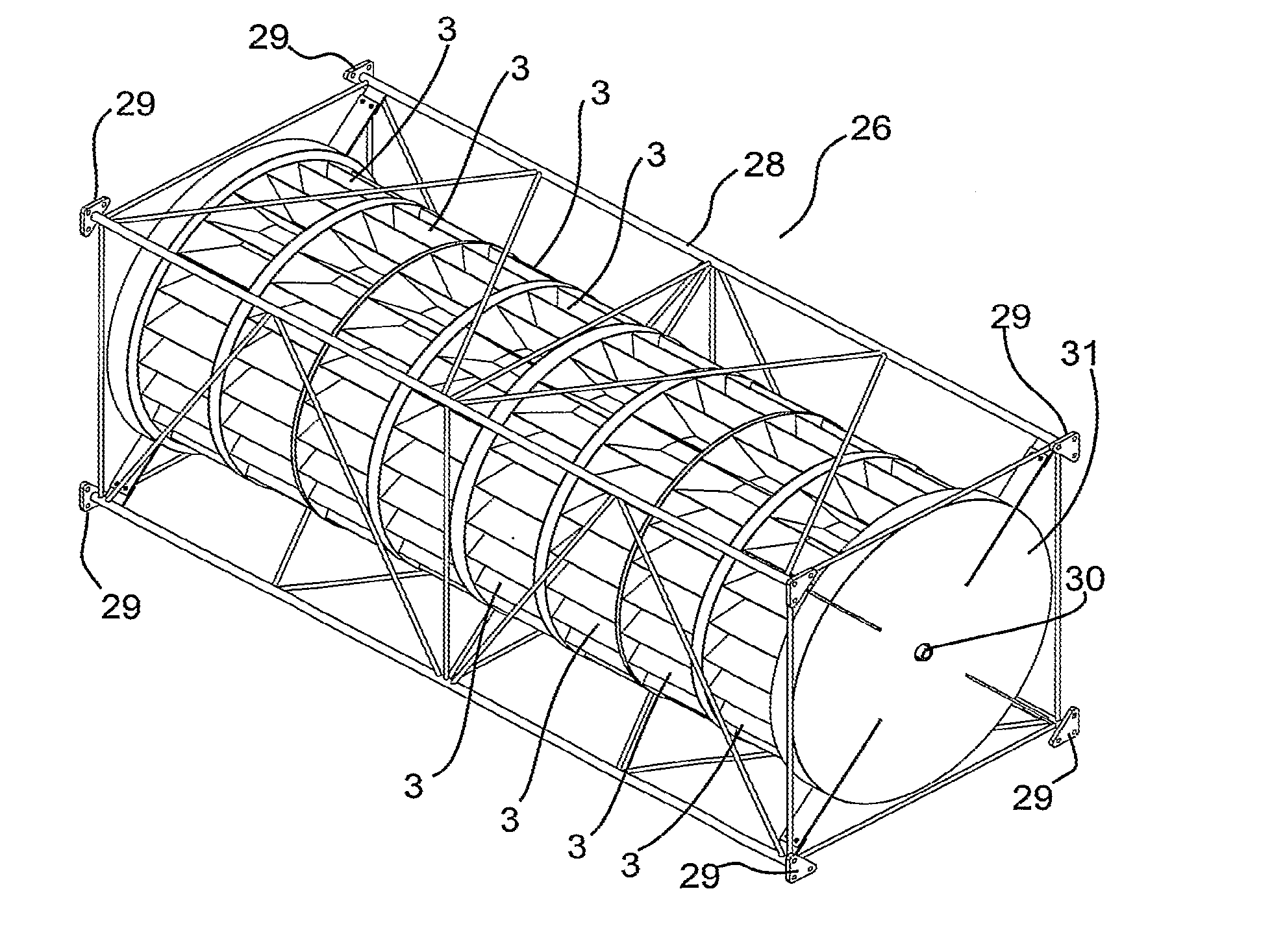
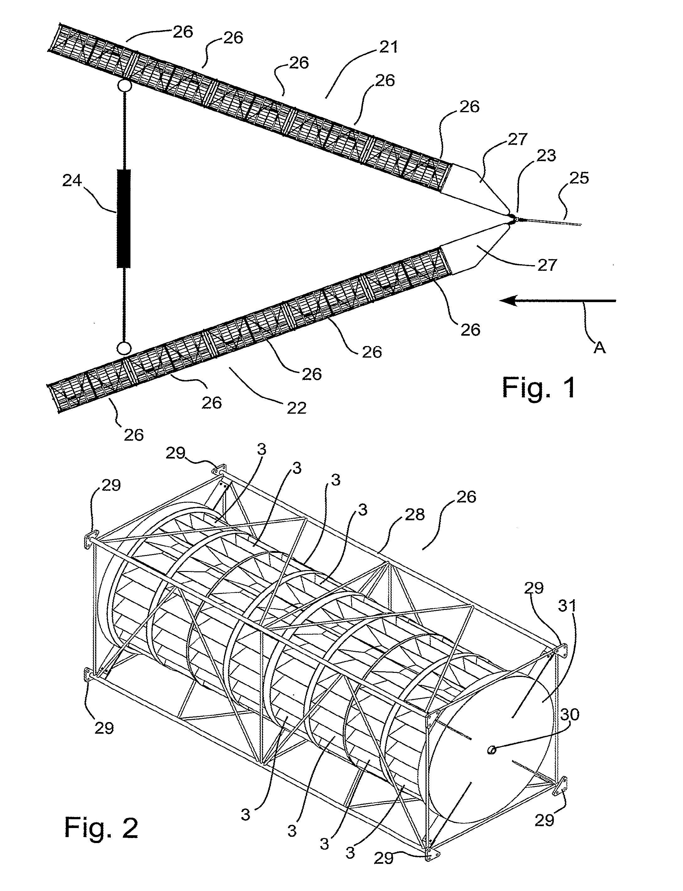
[0022]Thus, FIG. 1 shows an embodiment of a wave power plant according to the present invention, which wave power plant is a floating structure floating on the water surface area where waves are present that propagate in the direction of the arrow A. That wave power plant comprises two elongate, separate frame constructions 21, 22 that are hinged to each other via a hinge 23, said hinge also functioning as anchoring point for a mooring 25. Thereby the two separate frame constructions 21, 22 may be arranged according to choice at a mutual angle, and to that end a linear actuator 24 is configured, such as a hydraulic cylinder or a mechanical spindle.

[0023]By adjusting the length of the linear actuator 24, the angle between the two separate frame constructions 21, 22 can be adjusted manually or automatically as needed to the effect that the angle can be optimised with a view to obtaining the highest possible output effect or with a view to ensuring against breakdowns in stormy conditio...


PUM


Abstract

A wave power plant for extracting power from the wave movement of a water surface area, said wave power plant comprising a frame construction in which at least one rotor is journalled, and wherein the rotor is suspended in the frame construction on a rotor shaft which is, in the normal use situation of the wave power plant, essentially horizontal to the effect that the rotor is able to rotate about the rotor shaft which is retained in the frame construction, and wherein means are configured for maintaining each of the rotors partially immersed in a water surface area. The invention provides increased output efficiency of such wave power plant by the rotors being mounted on the rotor shaft via a free-running mechanism which is configured such that the rotor is able to transfer momentum to the rotor shaft essentially only when it rotates the one way about the rotor shaft.

Description

FIELD OF USE OF THE INVENTION[0001]The present invention relates to a wave power plant for extracting power from the wave movement of a water surface area, said wave power plant comprising a frame construction in which at least one rotor is journalled, and wherein the rotor is suspended in the frame construction on a rotor shaft which is, in the normal use situation of the wave power plant, essentially horizontal to the effect that the rotor is able to rotate about the rotor shaft which is retained in the frame construction, and wherein means are configured for maintaining each of the rotors partially immersed in a water surface area.STATE OF THE ART[0002]Today, many different embodiments of wave power plants are known that all share the feature that they utilise the energy which is provided when water is caused to move in a wave movement. A particular category of such wave power plants uses it to advantage that the water at the crest of a wave has a potential energy which is able t...

Claims


Application Information

Patent Timeline
Patent Type & Authority Applications(United States)
IPC IPC(8): F03B13/18
CPCF03B13/184Y02E10/30
Inventor LARSEN, TOMMY
Owner WEPTOS
Why Eureka
Try Eureka