
Spray nozzle assembly with impingement post-diffuser

a technology of diffuser and spray nozzle, which is applied in the direction of dispersed particle separation, lighting and heating apparatus, and separation processes, etc., can solve the problems of degrading performance, frequent and costly cleaning of the air cap, and spraying off, etc., and achieves the effect of improving spray performan

Active Publication Date: 2015-01-29
SPRAYING SYST
View PDF6 Cites 36 Cited by
  • Summary
  • Abstract
  • Description
  • Claims
  • Application Information

AI Technical Summary

Benefits of technology

The present invention provides an improved spray nozzle assembly for atomizing liquids in gas scrubbing and other applications. The design prevents buildup on the nozzle assembly and minimizes wear to the air cap. It is simple in construction and can be easily retrofitted in the field. This results in better spray performance and economical manufacture and retrofitting.

Problems solved by technology

During operation, fine particles of the high pressure discharging flow streams from the plurality of discharge orifices can migrate inwardly back toward the nozzle and create a heavy buildup of particulate matter about the discharge orifices that choke off the spray and significantly degrade performance.
This creates the need for frequent costly cleaning of the air cap of such buildup.
However, the increased surface areas of such angled discharge orifices can be subject to substantial wear in only a few days, as depicted in FIG. 7 by the wear “w” in the discharge orifices of an air cap of a prior art spray nozzle assembly, necessitating costly field repair or replacement.

Method used


Image

  • Spray nozzle assembly with impingement post-diffuser
  • Spray nozzle assembly with impingement post-diffuser
  • Spray nozzle assembly with impingement post-diffuser

Examples


Embodiment Construction

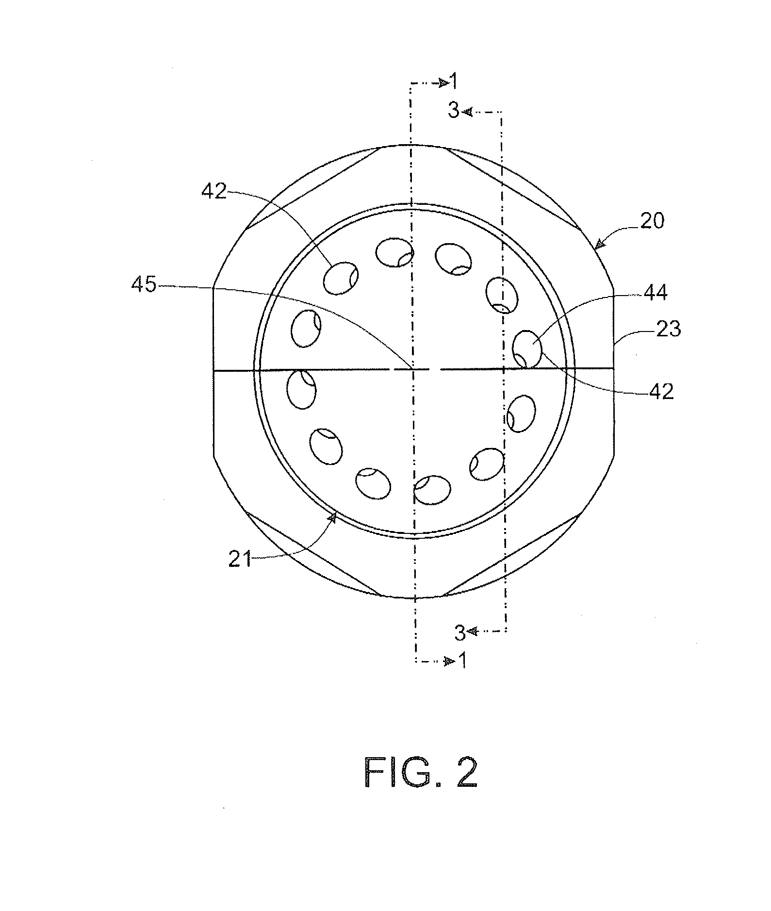
[0017]Referring now further to the drawings, and particularly FIG. 1, there is shown an illustrative internal-mix, pressurized air-atomizing spray nozzle assembly 10 in accordance with the invention connected to a conventional fluid supply manifold 11. The fluid supply manifold 11 in this case includes a central pressurized liquid supply passage 12 and a plurality of pressurized air supply passages 14 in surrounding relation to the liquid supply passage 12. The air passages 14 in this instance communicate with an annular manifold air passage 15 at a downstream end of the fluid supply manifold 11.

[0018]The illustrated spray nozzle assembly 10 basically comprise a nozzle body 20, a downstream air cap 21, and an air guide 22 interposed between the nozzle body 20 and air cap 21. The nozzle body 20 in this case is in the form of a multipart fluid supply subassembly comprising an outer annular body member 23 and an inner axial liquid supply tube 24 fixed therein which defines a liquid flo...


PUM


Abstract

An internal mix air atomizing spray nozzle assembly having a nozzle body that defines a central liquid flow passage, an air guide for directing pressurized air within the nozzle, and a downstream air cap having an upstanding impingement post and a plurality of discharge orifice defining passages about the impingement post. The air cap passages each are oriented at compound angle with respect to a central axis for discharging atomized liquid flow streams in a conical spray pattern swirling in a predetermined rotative direction about the central axis, and the impingement post has a diffuser cap that defines a flat central liquid impingement surface and an outer annular array of non radial diffuser veins for directing the atomized liquid and pressurized air in a swirling fashion about the impingement post in the same relative direction as the swirling spray pattern from the air cap passages.

Description

FIELD OF THE INVENTION[0001]The present invention relates generally to spray nozzle assemblies, and more particularly, to pressurized air internal mix spray nozzle assemblies in which liquid is atomized by pressurized air prior to discharge from the nozzle.BACKGROUND OF THE INVENTION[0002]Internal mix spray nozzle assemblies are known that utilize pressurized air for breaking down liquid into relatively small size particles. Such spray nozzle assemblies have particular utility in gas scrubbing applications, such as where lime slurry or the like is atomized and sprayed into a discharging stream of combustion gases for removing sulfur dioxide or other combustion byproducts. For efficient combustion gas scrubbing, it is necessary that the slurry be atomized into a very fine liquid particle spray.[0003]Such spray nozzle assemblies commonly direct the finely atomized liquid from a plurality of circumferentially spaced discharge orifices of an air cap of the nozzle so as to generate an ou...

Claims


Application Information

Patent Timeline
IPC IPC(8): B05B7/10B05B7/08
CPCB05B7/0892B05B7/10B01D47/06B05B7/045B05B7/0466B05B7/0876B01D53/185B01D53/504B01D53/80F23J15/003F23D11/103B01D2251/404B01D2257/302B01D2258/0283F23D2900/00003F23D2900/00018F23D2900/11001B05B1/26B05B15/18B05B7/0483
Inventor VIDUSEK, DANIELPATEL, BANDISH
Owner SPRAYING SYST
Learn More