
Oil Well Gas Lift by Hydrogen Production Through Produced Water Electrolysis Completion

a technology of electrolysis and production of hydrogen, which is applied in the direction of fluid removal, earthwork drilling and mining, borehole/well accessories, etc., can solve the problems of reducing the efficiency and effectiveness of the production system, facing the challenge of producing, etc., and achieves the effect of reducing the hydrostatic pressure on the gas bubbles and reducing the head pressur

Active Publication Date: 2015-01-29
SAUDI ARABIAN OIL CO
View PDF9 Cites 14 Cited by
  • Summary
  • Abstract
  • Description
  • Claims
  • Application Information

AI Technical Summary

Benefits of technology

The patent describes a method called artificial lift that helps to increase the production of oil from underground reservoirs. The method involves using a mechanical process to increase the flow of oil from the reservoir to the surface. This is done by using a gas with low solubility in the oil to create bubbles that rise upward with the oil as it flows. These bubbles decrease the pressure on top of the oil, allowing it to flow more easily. This decreases the density of the oil in the production fluid, which in turn reduces the pressure on the oil downhole, allowing more oil to flow out of the reservoir. Overall, this method helps to increase oil production from underground reservoirs.

Problems solved by technology

Regardless of mechanically restricting production fluid inlet rate to mitigate the effects of “coning” or “fingering” of water through hydrocarbons in the hydrocarbon-bearing formation, aging oil fields still face the challenge of producing “wet oil”.
This “water cut” reduces the efficiency and effectiveness of the production system by bringing formation water to the surface.

Method used


Image

  • Oil Well Gas Lift by Hydrogen Production Through Produced Water Electrolysis Completion
  • Oil Well Gas Lift by Hydrogen Production Through Produced Water Electrolysis Completion
  • Oil Well Gas Lift by Hydrogen Production Through Produced Water Electrolysis Completion

Examples


Embodiment Construction

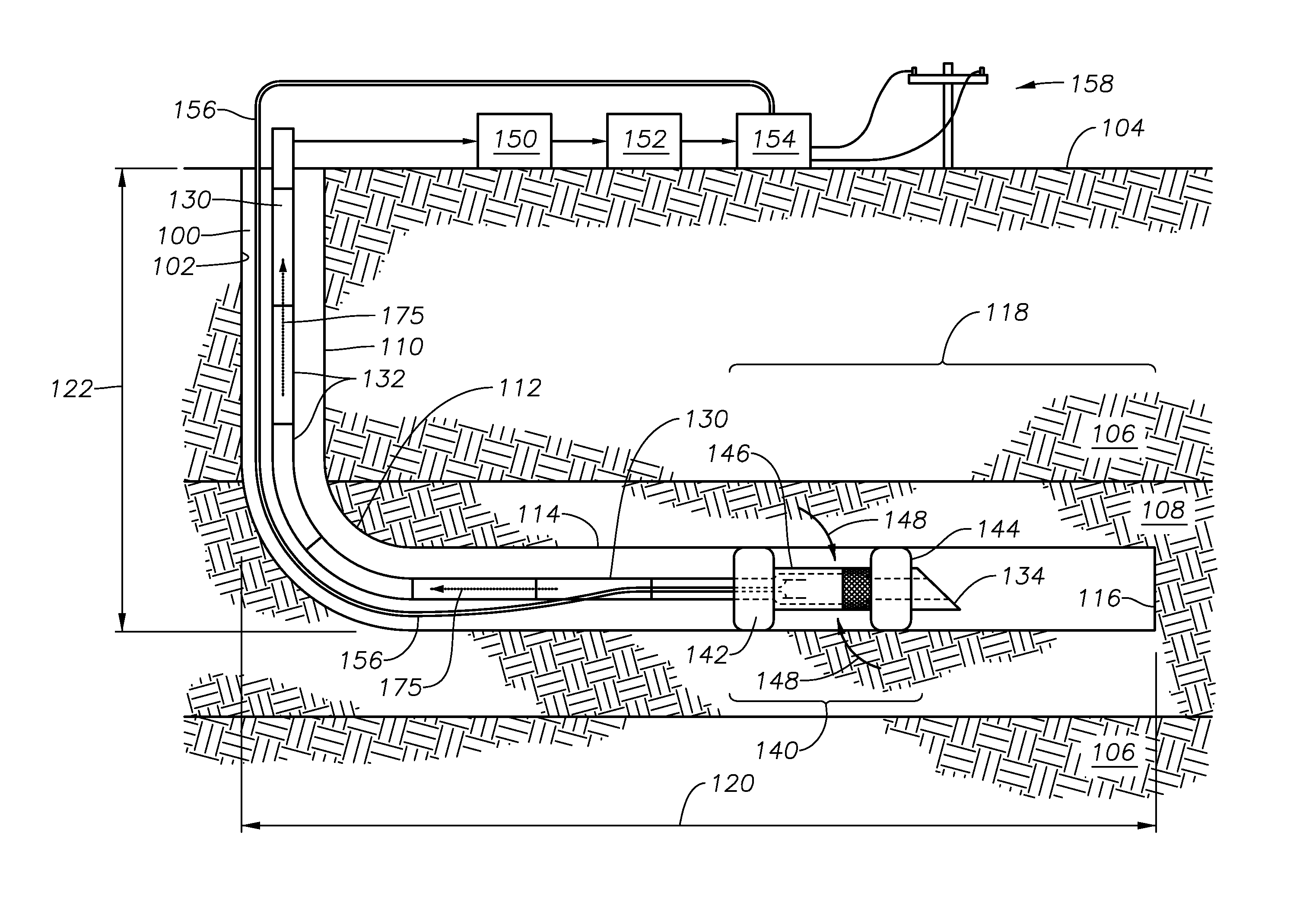
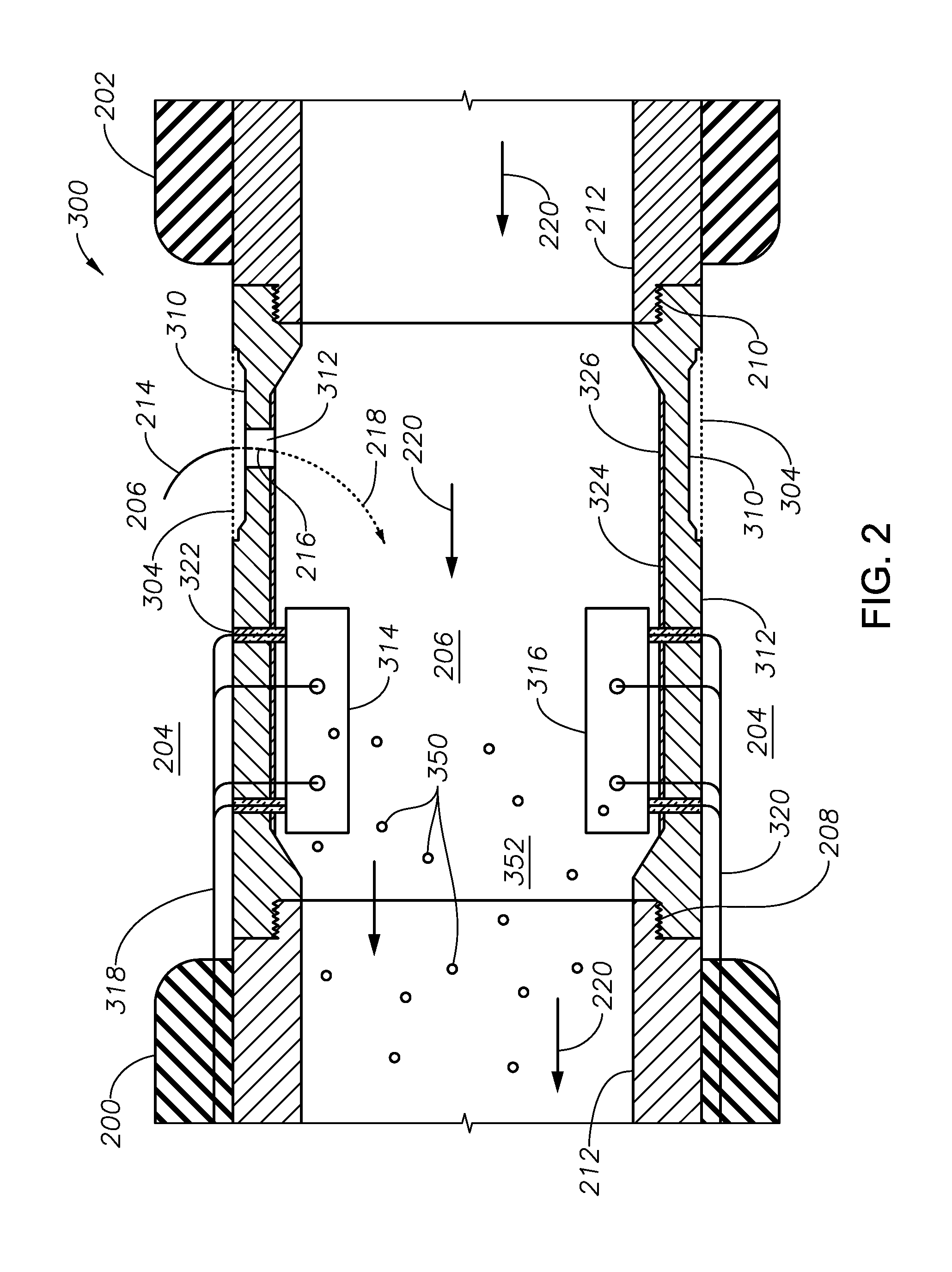
[0020]The Specification, which includes the Summary of invention, Brief Description of the Drawings and the Detailed Description of the Preferred Embodiments, and the appended Claims refer to particular features (including process or method steps) of the invention. Those of skill in the art understand that the invention includes all possible combinations and uses of particular features described in the Specification. Those of skill in the art understand that the invention is not limited to or by the description of embodiments given in the Specification. The inventive subject matter is not restricted except only in the spirit of the Specification and appended Claims.

[0021]Those of skill in the art also understand that the terminology used for describing particular embodiments does not limit the scope or breadth of the invention. In interpreting the Specification and appended Claims, all terms should be interpreted in the broadest possible manner consistent within the context of each ...


PUM


Abstract

A method of using an electrochemical gas lift apparatus to induce artificial gas lift in a production fluid includes introducing the electrochemical gas lift apparatus into a well bore having a production zone, operating the electrochemical gas lift apparatus such that a combination of hydrocarbon fluid and formation water is introduced into the interior of the electrochemical gas lift apparatus, introducing electrical power to the electrochemical gas lift apparatus such that at least a portion of formation water in the interior of the electrochemical gas lift apparatus converts into product gases, operating the electrochemical gas lift apparatus such that the product gases form product gas bubbles in the interior of the electrochemical gas lift apparatus, and operating the electrochemical gas lift apparatus such that production fluid forms in the interior of the electrochemical gas lift apparatus. The production fluid comprises hydrocarbon fluid, unconverted formation water and product gas bubbles.

Description

CROSS-REFERENCE TO RELATED PATENT APPLICATIONS[0001]This application claims priority from U.S. Provisional Application No. 61 / 858,700, filed Jul. 26, 2013. For purposes of United States patent practice, this application incorporates the contents of the Provisional Application by reference in its entirety.BACKGROUND OF THE INVENTION[0002]1. Field of the Invention[0003]The field of invention relates to providing artificial lift to a well producing hydrocarbon fluid. More specifically, the field relates to providing artificial lift using an electrochemical gas lift apparatus, method of use, and system.[0004]2. Description of the Related Art[0005]In drilling long, horizontal wells, the well bore traversing through the hydrocarbon-bearing formation encounters areas where the porosity and conductivity is not homogenous. The hydrocarbon-bearing formation can include areas of greater permeability that conduct water through the formation at a greater rate towards a production point than hydr...

Claims


Application Information

Patent Timeline
Patent Type & Authority Applications(United States)
IPC IPC(8): E21B43/12
CPCE21B43/122E21B43/121
Inventor AL-MULHEM, ABDULRAHMAN ABDULAZIZNOUI-MEHIDI, MOHAMED NABIL
Owner SAUDI ARABIAN OIL CO
Learn More