
Device And Method For Measuring Wave Motion

a wave motion and measurement device technology, applied in the field of measuring devices and methods for wave motion, can solve the problems of increasing the overall cost, high cost of custom-designed sensors, and inability to obtain accurate wave motion estimates in real-time, and achieve the effect of accurate wave motion information

Inactive Publication Date: 2015-01-22
SEA ENG
View PDF2 Cites 21 Cited by
  • Summary
  • Abstract
  • Description
  • Claims
  • Application Information

AI Technical Summary

Benefits of technology

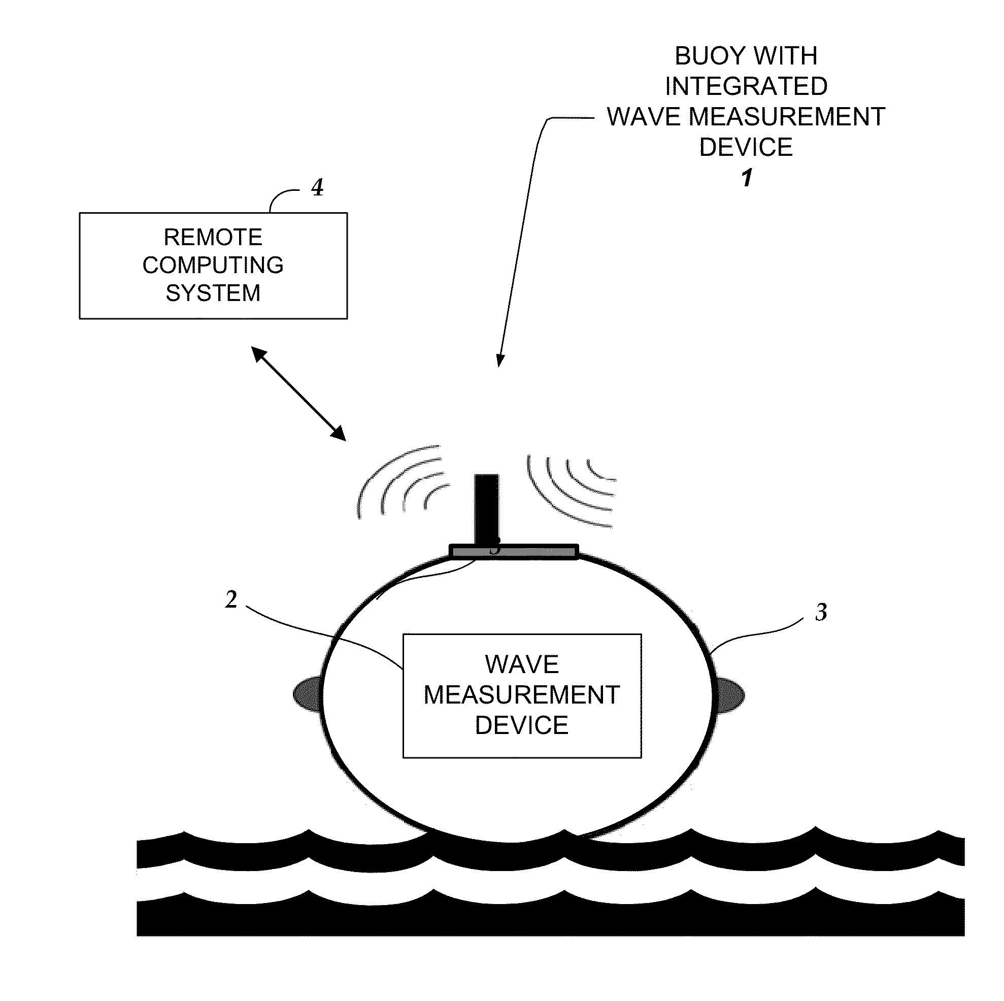
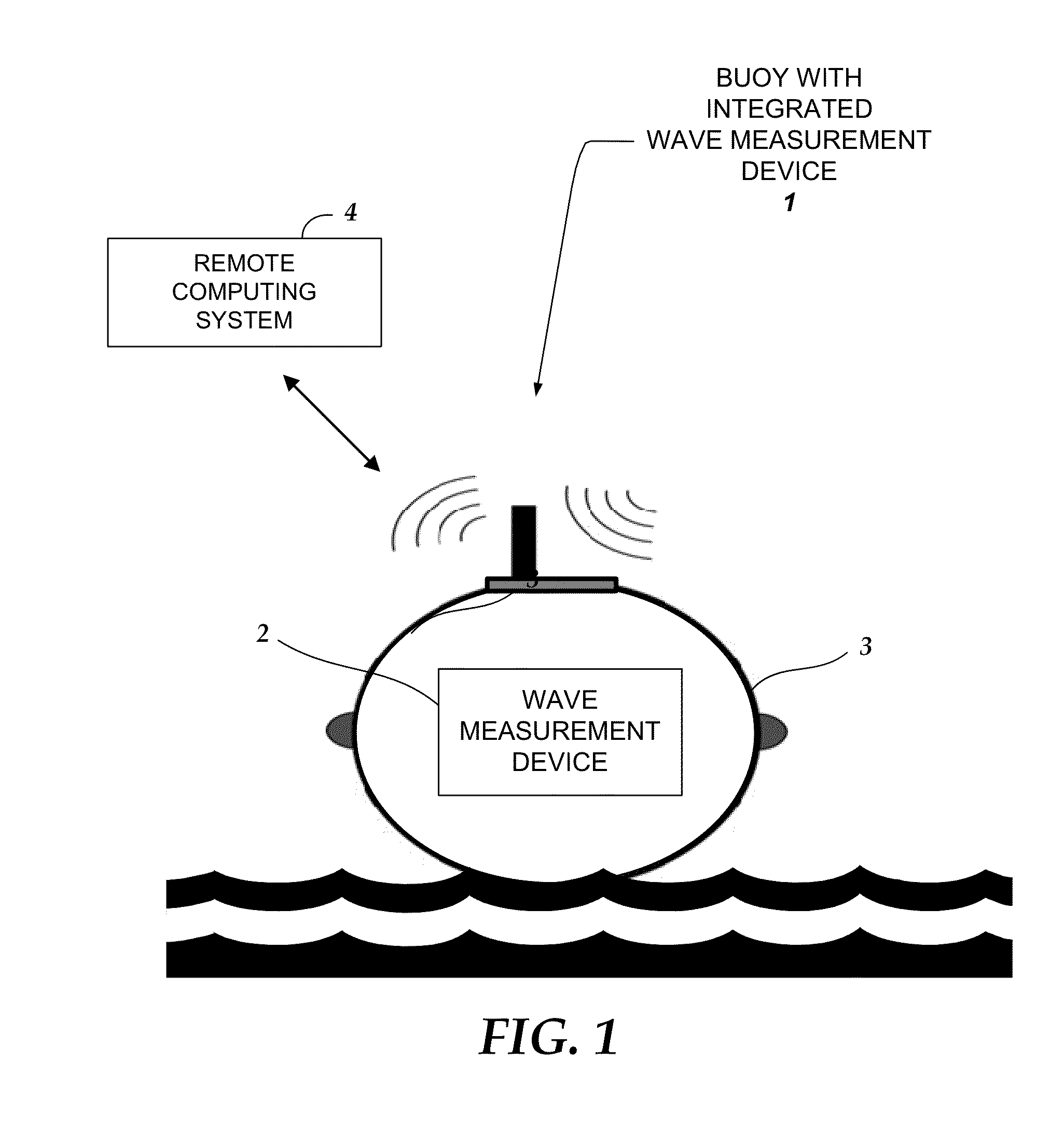
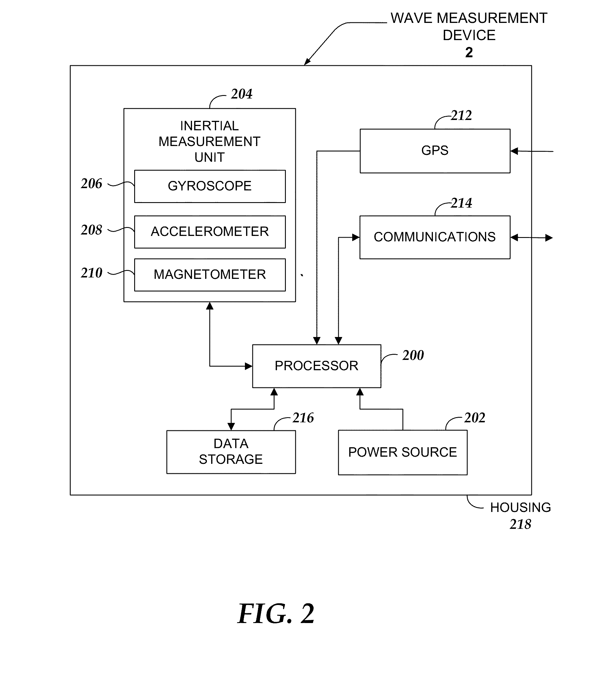
The patent describes a wave measuring electronics device that is integrated within a buoy. The device uses software algorithms to process data from motion sensors in the buoy, allowing for accurate detection of wave motion. The invention is designed to provide full 3-dimensional motion detection by fusing data from accelerometers, gyroscopes, and a magnetometer. The device can be used in oceans or other bodies of water and can include GPS for position tracking. The invention allows for the estimation of wave parameters such as height, period, and directional wave spectra. Overall, the invention provides a technical innovation for accurately measuring wave motion in real-time.

Problems solved by technology

However, there have not been good solutions for obtaining accurate estimates of wave motion in real-time based on sensors embedded in surface following ocean buoys.
These custom designed sensors have a high cost and are physically limited in the range of measurements they can make.
These custom sensors subsequently increase the overall expense and limit the quality of the motion sensing data they can measure.
Additionally, as described in U.S. Pat. No. 8,195,395 by Chung-Chu Teng, et al., recent state-of-the art methods for computing directional wave spectra, in which the processing of buoy pitch and roll is based on acceleration alone, limit the fidelity and quality of the derived wave motion.
For example such methods have the potential for singularities such as gimbal lock and may introduce excess noise due to the reliance on one set of sensor data, namely, sensor data from an accelerometer, to determine rotation.
The processing based on measurements from these custom sensors is limited to spectral components which limit the capabilities to wave measurements over longer periods of time (typically 20 minutes).
Thus, prior art approaches are not capable of providing an accurate estimate of directional wave motion in real-time.
However, the signal output of such MEMS are typically low resolution and are subject to high noise levels.

Method used


Image

  • Device And Method For Measuring Wave Motion
  • Device And Method For Measuring Wave Motion
  • Device And Method For Measuring Wave Motion

Examples


Embodiment Construction

[0032]The invention now will be described more fully hereinafter with reference to the accompanying drawings, which form a part hereof, and which show, by way of illustration, specific exemplary embodiments by which the invention may be practiced. This invention may, however, be embodied in many different forms and should not be construed as limited to the embodiments set forth herein; rather, these embodiments are provided so that this disclosure will be thorough and complete, and will fully convey the scope of the invention to those skilled in the art. Among other things, the invention may be embodied as methods, processes, systems, business methods or devices. Accordingly, the present invention may take the form of an entirely hardware embodiment, an entirely software embodiment or an embodiment combining software and hardware aspects. The following detailed description is, therefore, not to be taken in a limiting sense.

[0033]As used herein the following terms have the meanings g...


PUM


Abstract

Embodiments are directed towards a wave measuring electronics device that is integrated within a buoy and the buoy is moored in an ocean. The wave measurement device performs a computer-implemented method for estimating wave motion, including receiving 3D sensor data from each of an accelerometer and a gyroscope, determining, an absolute orientation of the buoy based on said 3D sensor data; and estimating, the true earth acceleration of the buoy over a specified time interval.

Description

REFERENCE TO RELATED APPLICATIONS[0001]This application claims benefit of U.S. Provisional Application No. 61 / 857,057, entitled A Device And Method For Measuring Wave Motion, filed on Jul. 22, 2013 by inventor Craig A. Jones.GOVERNMENT LICENSE RIGHTS[0002]This invention was made with government support under ARPA-E Award No. DE-AR0000305 awarded by THE U.S. Department of Energy. The government has certain rights in the invention.BACKGROUND[0003]Spectral approaches to estimating wave motion based on surface following buoy motions have been known for over 50 years. However, there have not been good solutions for obtaining accurate estimates of wave motion in real-time based on sensors embedded in surface following ocean buoys.[0004]The present industry standard surface wave measurement devices, referred to hereinbelow as “standard buoys,” perform surface measurements of wave elevation, acceleration, and surface tilts from horizontal directions to determine a non-directional, or omnidi...

Claims


Application Information

Patent Timeline
IPC IPC(8): G01C13/00
CPCG01C13/002G01C13/004
Inventor JONES, CRAIG A.SPADA, GRACE CHANG
Owner SEA ENG
Learn More