Vehicle steering system
- Summary
- Abstract
- Description
- Claims
- Application Information
AI Technical Summary
Benefits of technology
Problems solved by technology
Method used
Image

Examples
first embodiment
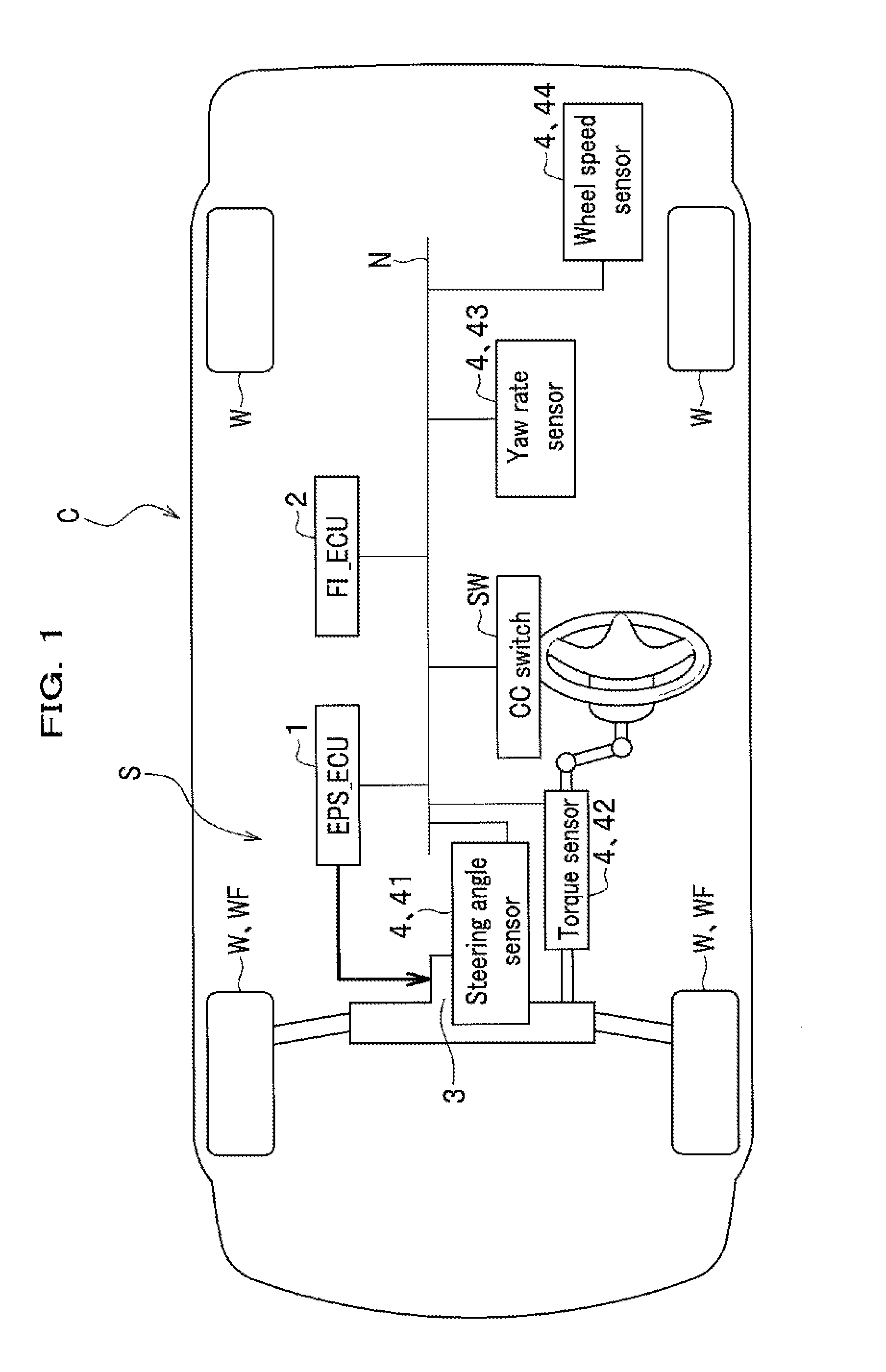
[0065][OVERALL CONFIGURATION]FIG. 1 is a diagram schematically showing the overall configuration of a vehicle C equipped with a vehicle steering system S according to embodiments of the present invention. As shown in FIG. 1, the vehicle C is a four-wheeled vehicle that includes an internal combustion engine (not shown) and four wheels W. Wheels WF show steerable wheels. The vehicle steering system S is installed in the vehicle C and configured with an electric power steering system including an EPS_ECU 1 that is an ECU (Electronic Control Unit) for controlling electric power steering (EPS) and an electric motor 3 for steering. This electric power steering system is a well-known system for providing assist by driving the motor 3 so as to relieve a steering effort of the driver required for steering the wheels W. In addition, the vehicle C includes an FI_ECU 2 that is an ECU for controlling fuel injection (FI).
[0066]The EPS_ECU 1 is connected with various sensors 4, including a steeri...
second embodiment
[0194]Next, a description will be given of a vehicle steering system according to a second embodiment of the present invention, with reference to FIGS. 8A and 8B.
FIG. 8A is a block diagram showing a schematic configuration of a vehicle steering system according to a second embodiment of the present invention. FIG. 8B is a diagram showing an example of adjusting the mapping information of a current value relative to a steering angle, which information is set in the steering effort assist current value setting unit according to the second embodiment, for increasing the control amount of the anti-unidirectional-drift control. In the horizontal axis (steering angle) of the chart shown in FIG. 8B, positive and negative values represent rightward and leftward steering angles, respectively.
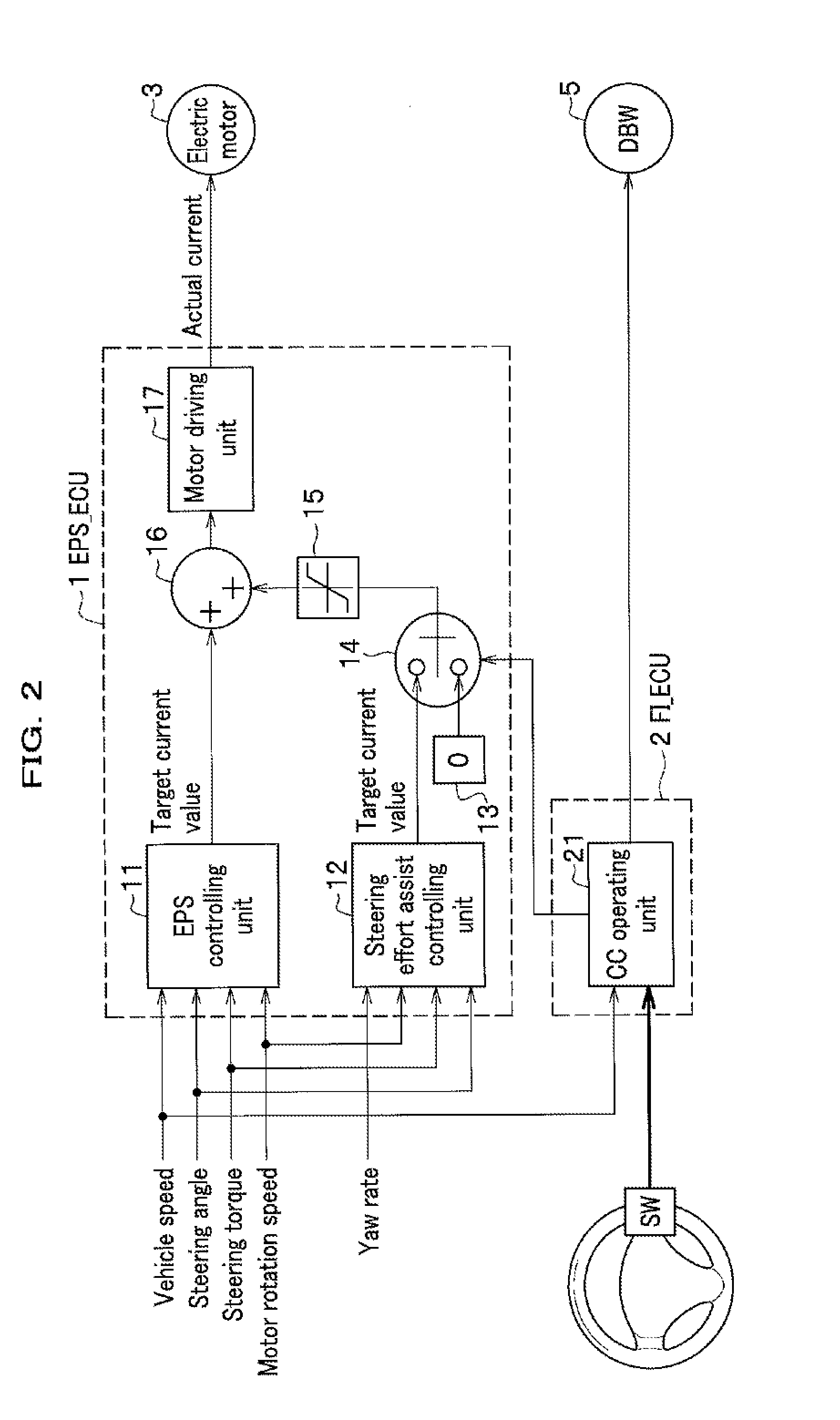
[0195]The vehicle steering system according to the second embodiment shown in FIG. 8A corresponds to the vehicle steering system according to the first embodiment shown in FIG. 2. Common members in both ...
third embodiment
[0211]In the second embodiment, a description has been given of an example in which, for example, in response to the steering effort on the steering wheel H by the driver being weakened, the control amount for the anti-unidirectional-drift control when the steering effort is weakened is increased, as compared to the control amount for the anti-unidirectional-drift control when the steering effort is not weakened.
[0212]In contrast, in the third embodiment, an embodiment will be described, with reference to FIGS. 9A and 9B, in which, contrary to the second embodiment, the control amount for the anti-unidirectional-drift control (target anti-unidirectional-drift current value) is decreased. Note that decreasing the control amount for the anti-unidirectional-drift control includes stopping the anti-unidirectional-drift control.
[0213]FIG. 9A is a block diagram showing a schematic configuration of a vehicle steering system according to a third embodiment of the present invention. FIG. 9B ...
PUM
 Abstract
Description
Claims
Application Information
 - R&D
- Intellectual Property
- Life Sciences
- Materials
- Tech Scout
- Unparalleled Data Quality
- Higher Quality Content
- 60% Fewer Hallucinations
Browse by: Latest US Patents, China's latest patents, Technical Efficacy Thesaurus, Application Domain, Technology Topic, Popular Technical Reports.
© 2025 PatSnap. All rights reserved.Legal|Privacy policy|Modern Slavery Act Transparency Statement|Sitemap|About US| Contact US: help@patsnap.com