
Aerodynamic Variable Cross-Section Airfoil and Constant Lateral Surface Area Truss

a technology of airfoil and constant lateral surface area, which is applied in the direction of machine/engine, vessel construction, transportation and packaging, etc., can solve the problems of not being aerodynamically efficient and severely impairing performance, and achieve the effect of less complexity and better emulation

Inactive Publication Date: 2015-01-22
EGBERT NITIN KITCHLEY
View PDF30 Cites 6 Cited by
  • Summary
  • Abstract
  • Description
  • Claims
  • Application Information

AI Technical Summary

Benefits of technology

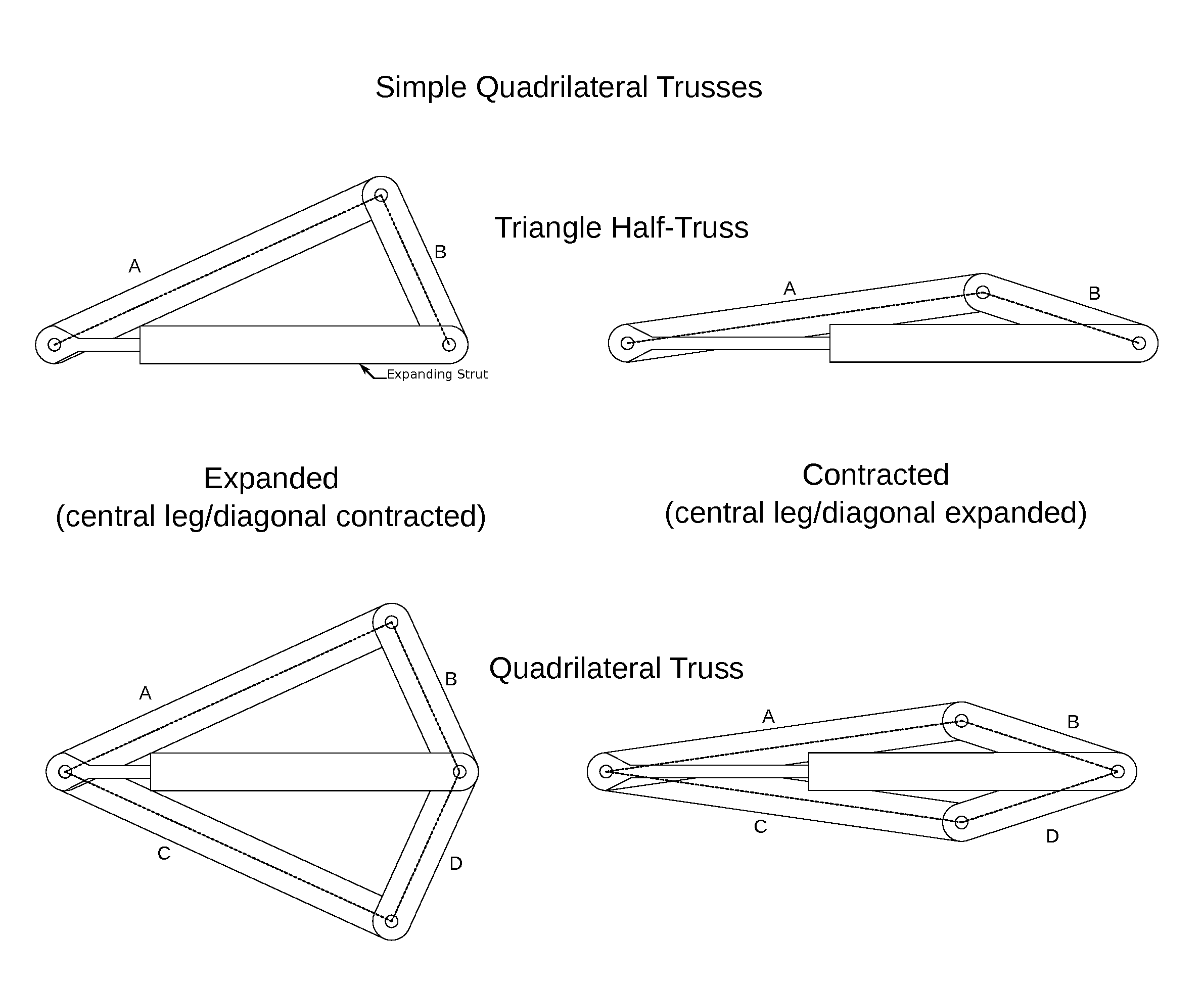
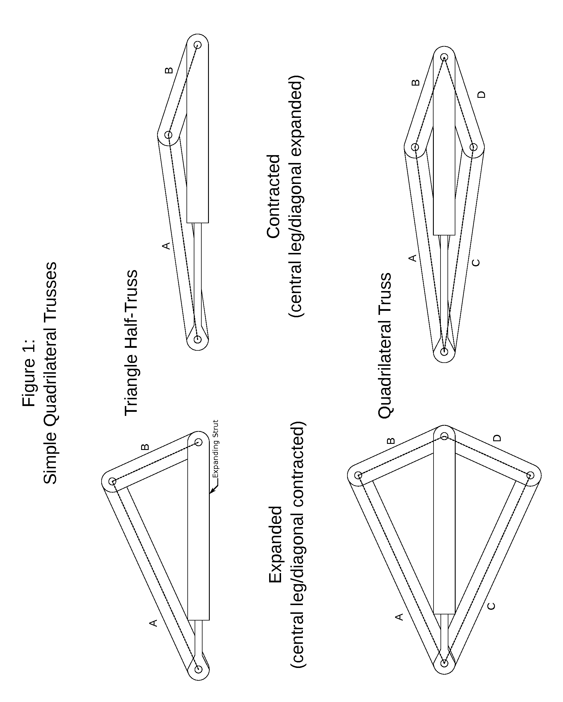
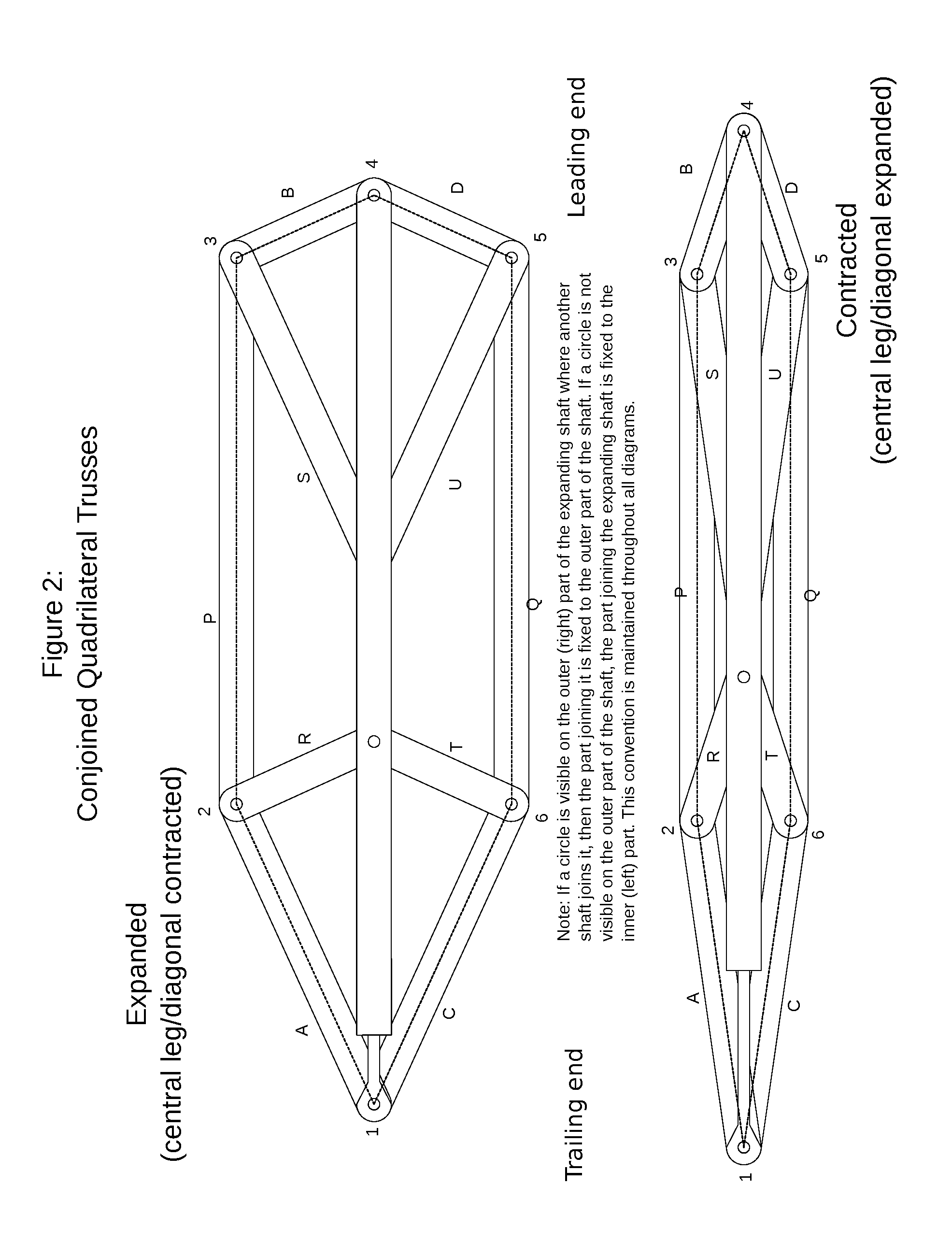
The patent describes trusses that use pivots to connect segments. These trusses can have curved edges on the segments as long as they end at the pivot point. This design allows for a better emulation of the desired airfoil shape with less complexity in the truss. Additionally, plates can be affixed along the length of each segment to improve strength and stability. These plates can be continuous or discontinuous with neighboring trusses.

Problems solved by technology

This could be accomplished by covering an expanding truss with an elastic material, but this is inefficient because to increase the buoyancy, work must be done against both environmental pressure and the elastic material.
A chamber of variable buoyancy could also be made by a balloon of non-elastic material which is then folded or tied down to reduce the volume, but this is by necessity not aerodynamically efficient in one of the given configurations, and a misfold or an unexpected wrinkling of the material will severely impair performance.

Method used


Image

  • Aerodynamic Variable Cross-Section Airfoil and Constant Lateral Surface Area Truss
  • Aerodynamic Variable Cross-Section Airfoil and Constant Lateral Surface Area Truss
  • Aerodynamic Variable Cross-Section Airfoil and Constant Lateral Surface Area Truss

Examples


Embodiment Construction

[0036]Fixing each truss to expand by the same amount as the others may be accomplished as simply as having a single rod join the leading edges of the trusses and another rod joining the trailing edges of the trusses in every shared expandable strut present. The airfoil may also have a curved leading or trailing edge, but note that it is necessary for the enclosing material to have some elasticity to conform to the frame in this case. The rods joining the leading rails need only be curved to achieve this.

[0037]Since it is preferable to have the sheet of material around the airfoil frame wrinkle and fold as little as possible, it is best to construct the truss with the majority of the structure within the perimeter of the truss. Therefore the individual segments of each half truss may be constructed with a bent shape to ensure that the main body of the segment lies within the perimeter of the truss as in FIG. 7. This way, most of the enclosing sheet material may lie along the perimete...


PUM


Abstract

The invention provides a mechanism for an airtight airfoil with variable cross section that can lower its average density below that of the medium in which it is used, providing additional bouyancy and reducing the effective weight of any craft to which it may be affixed. The outside of the airfoil is formed by a sheet of material that is impermeable to the medium in which the foil is used. This sheet is affixed to several points on an internal expandable frame. The cross-sectional perimeter of the frame remains constant throughout the expansion of the frame, minimizing wear on the enclosing sheet of material. Because the length of the sheet remains constant through the expansion process, the sheet need not be elastic, and may even be replaced by rigid plates of material. By providing a variable source of buoyancy, this foil enables lower speed and lower power applications than regular foils. By providing a smoothly variable airfoil cross-section, this foil enables higher performance in a wider variety of aerodynamic conditions.

Description

CROSS-REFERENCES TO RELATED APPLICATIONS[0001]U.S. Pat. No. 5,005,783—Taylor[0002]U.S. Pat. No. 1,424,491—Langevin[0003]U.S. Pat. No. 3,970,270—PittetFIELD OF INVENTION[0004]This invention relates to methods of reducing the effective weight or increasing the buoyancy of any vehicle or craft that requires an airfoil or hydrofoil, as well as applications that require dynamic changes in the cross-section of an airfoil or hydrofoil.BACKGROUND OF INVENTION[0005]In recent years there has been an increase in military and commercial interest in small, lightweight aircraft. Making such aircraft lighter-than-air is often undesirable because it increases the need for maintenance as the source of the buoyancy is often a bladder or balloon filled with a lighter-than-air gas, which when exposed to stress can tear or burst unpredictably and lose its utility. On the other hand, making such a craft only partially buoyant as an auxiliary form of support, rather than its only means of lift, can be hel...

Claims


Application Information

Patent Timeline
Patent Type & Authority Applications(United States)
IPC IPC(8): F15D1/12B64C3/14B63B1/24
CPCF15D1/12B64C3/14B63B1/248F15D1/10B64C1/34B64C3/48
Inventor EGBERT, NITIN, KITCHLEY
Owner EGBERT NITIN KITCHLEY
Learn More