Sound Processing System and Sound Processing Device
a technology of sound processing system and sound processing device, which is applied in the direction of earpiece/earphone attachment, ear mould/tip acoustic seal, earpiece/earphone attachment, etc., which can solve the problems of user forgetting that music is playing, power source exhausted, and operation is very inconvenient for the user
- Summary
- Abstract
- Description
- Claims
- Application Information
AI Technical Summary
Benefits of technology
Problems solved by technology
Method used
Image
Examples
first embodiment
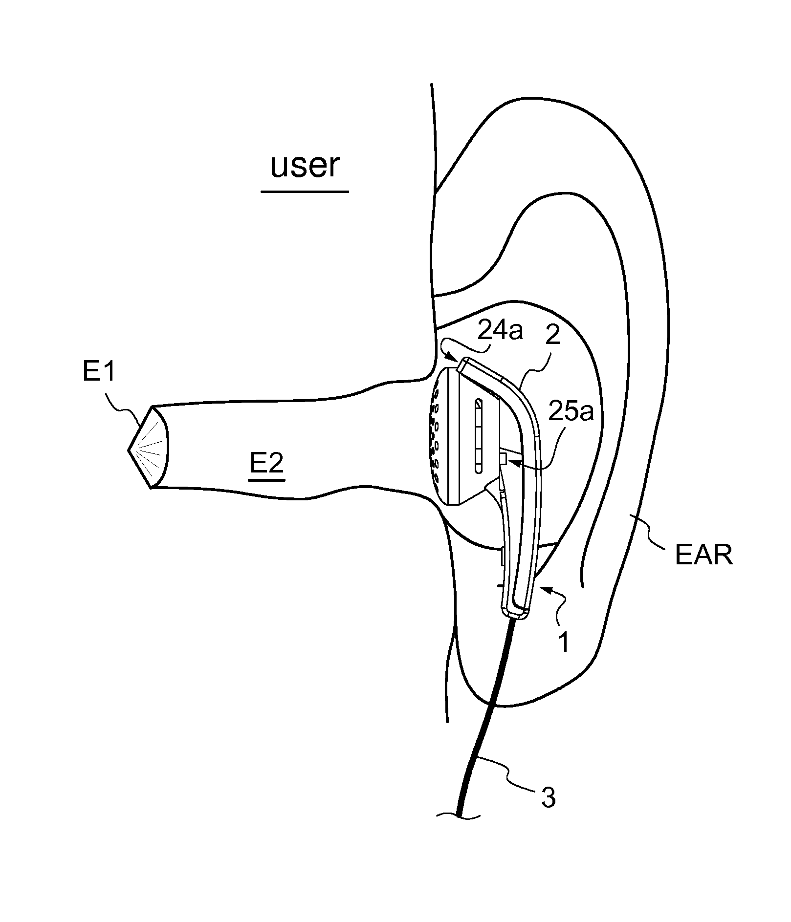
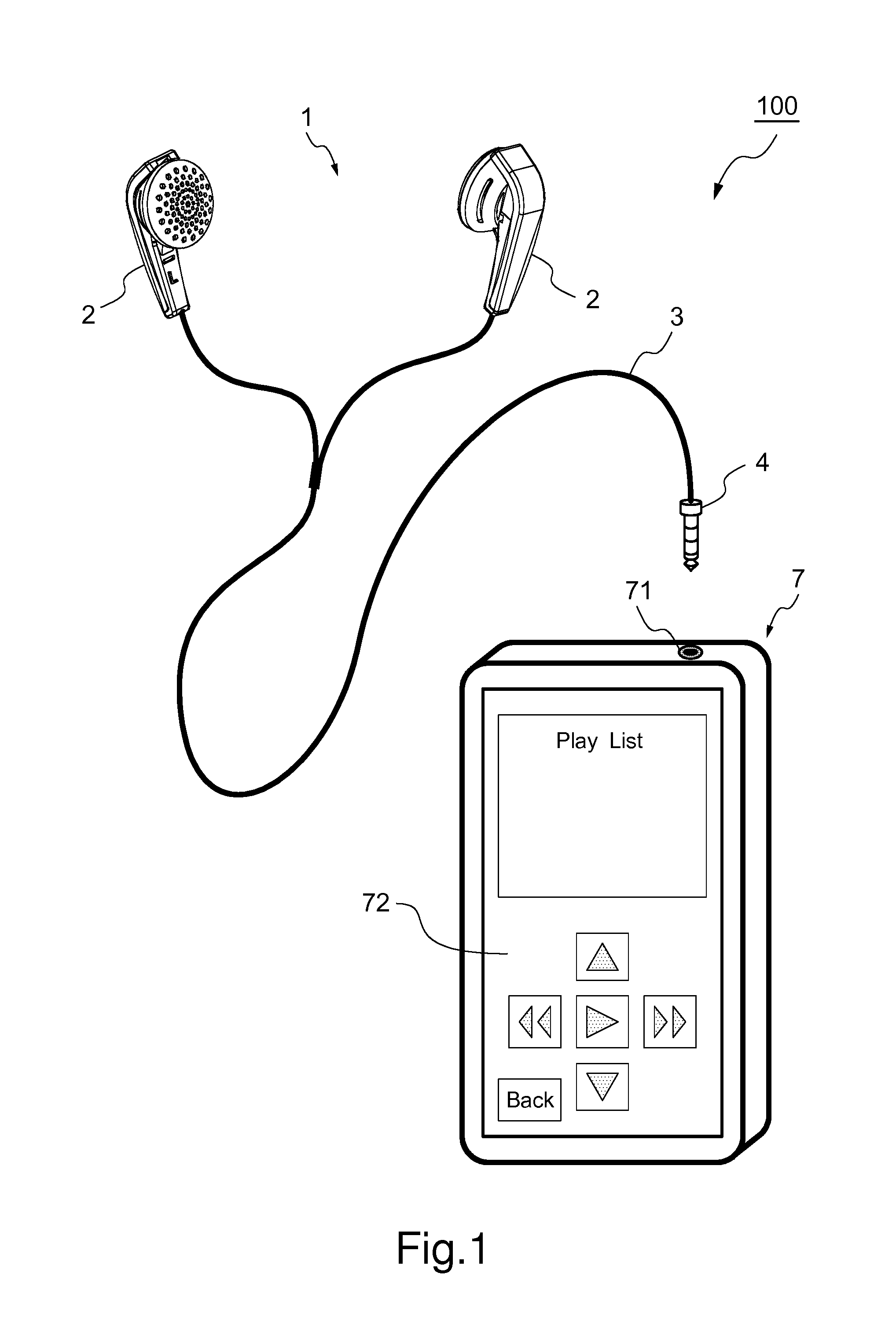
[0020]FIG. 1 is an external perspective view of a sound processing system. As illustrated in FIG. 1, in a sound processing system 100, an inner ear type earphone microphone 1 is connected to a smart phone 7. Note that, for easy understanding of a general structure of the earphone microphone 1, FIG. 1 illustrates a state before a plug 4 of the earphone microphone I is connected to an earphone jack 71 of the smart phone 7.
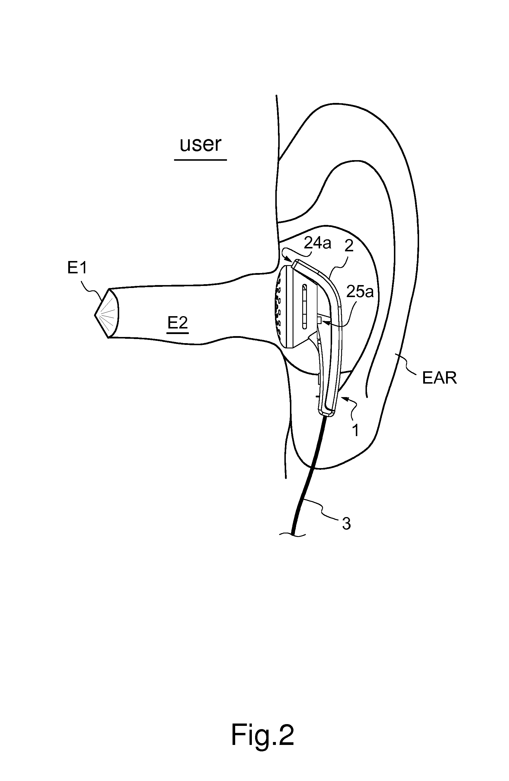
[0021]This earphone microphone 1 is a sound input / output device including two main bodies 2, a cable 3, and the four-electrode plug 4. Each main body 2, which is placed in the user's ear, outputs an output sound based on a sound signal sent from the smart phone 7, and collects input sounds (for example, user's speaking voice) from outside. A specific structure of the main body 2 will be described later. The cable 3 is a signal wire connected between each main body 2 and the plug 4. The cable 3 sends and receives signals between each main body 2 of the earphone microp...
second embodiment
[0050]Next, the earphone microphone 1 according to a second embodiment is described. FIG. 6 is a schematic cross-sectional view of a main body of the earphone microphone placed in the user's ear according to the second embodiment. In the second embodiment, instead of the sound input passage 24 and the first opening 24a, a third opening 26 is formed in a partition 23a separating the speaker 21 from the microphone 22. In addition, a space between the speaker 21 and the partition 23a functions as the sound input passage 24 and is communicated with the first sound input hole 22a through the third opening 26. Other than that is the same as the first embodiment. In the following description, the same structural element as the first embodiment is denoted by the same numeral or symbol, and description thereof is omitted.
[0051]Note that in FIG. 6, a broken line arrow indicates a propagation path of the output sound from the earphone microphone 1 to the external acoustic meatus E2. In additio...
third embodiment
[0055]Next, the earphone microphone 1 of a third embodiment is described. FIG. 7 is a schematic cross-sectional view of the main body of the earphone microphone placed in the user's ear according to the third embodiment. In the third embodiment, there is formed a through hole 27 communicating between a sound output surface 21a and the backside space of the speaker 21. In addition, the space between the speaker 21 and the partition 23a and the through hole 27 function as the sound input passage 24 and are communicated with the first sound input hole 22a through the third opening 26. Other than that is the same as the second embodiment. The same structural element as the second embodiment is denoted by the same numeral or symbol, and description thereof is omitted.
[0056]Note that in FIG. 7, a broken line arrow indicates a propagation path of the output sound from the earphone microphone 1 to the external acoustic meatus E2. In addition, a solid line arrow indicates a propagation path ...
PUM
 Abstract
Description
Claims
Application Information
 - R&D
- Intellectual Property
- Life Sciences
- Materials
- Tech Scout
- Unparalleled Data Quality
- Higher Quality Content
- 60% Fewer Hallucinations
Browse by: Latest US Patents, China's latest patents, Technical Efficacy Thesaurus, Application Domain, Technology Topic, Popular Technical Reports.
© 2025 PatSnap. All rights reserved.Legal|Privacy policy|Modern Slavery Act Transparency Statement|Sitemap|About US| Contact US: help@patsnap.com


