Linear actuator

a technology of linear actuators and actuators, applied in the direction of electrical equipment, mechanical energy handling, dynamo-electric machines, etc., can solve the problems of easy propagation of shaft distortion and damage of permanent magnets, and achieve the effect of easy propagation

Inactive Publication Date: 2015-01-15
KYB CORP
View PDF5 Cites 6 Cited by
  • Summary
  • Abstract
  • Description
  • Claims
  • Application Information

AI Technical Summary

Benefits of technology

[0003]The linear actuator described in JP2005-106242A includes a shaft with fixed permanent magnets, and in a fully extended state, the shaft is subjected to a compression load due to self thrust. Therefore, the distortion of the shaft is easily propagated to the permanent magnets, and the permanent magnets may be damaged.

Problems solved by technology

Therefore, the distortion of the shaft is easily propagated to the permanent magnets, and the permanent magnets may be damaged.

Method used


Image

  • Linear actuator
  • Linear actuator
  • Linear actuator

Examples


Embodiment Construction

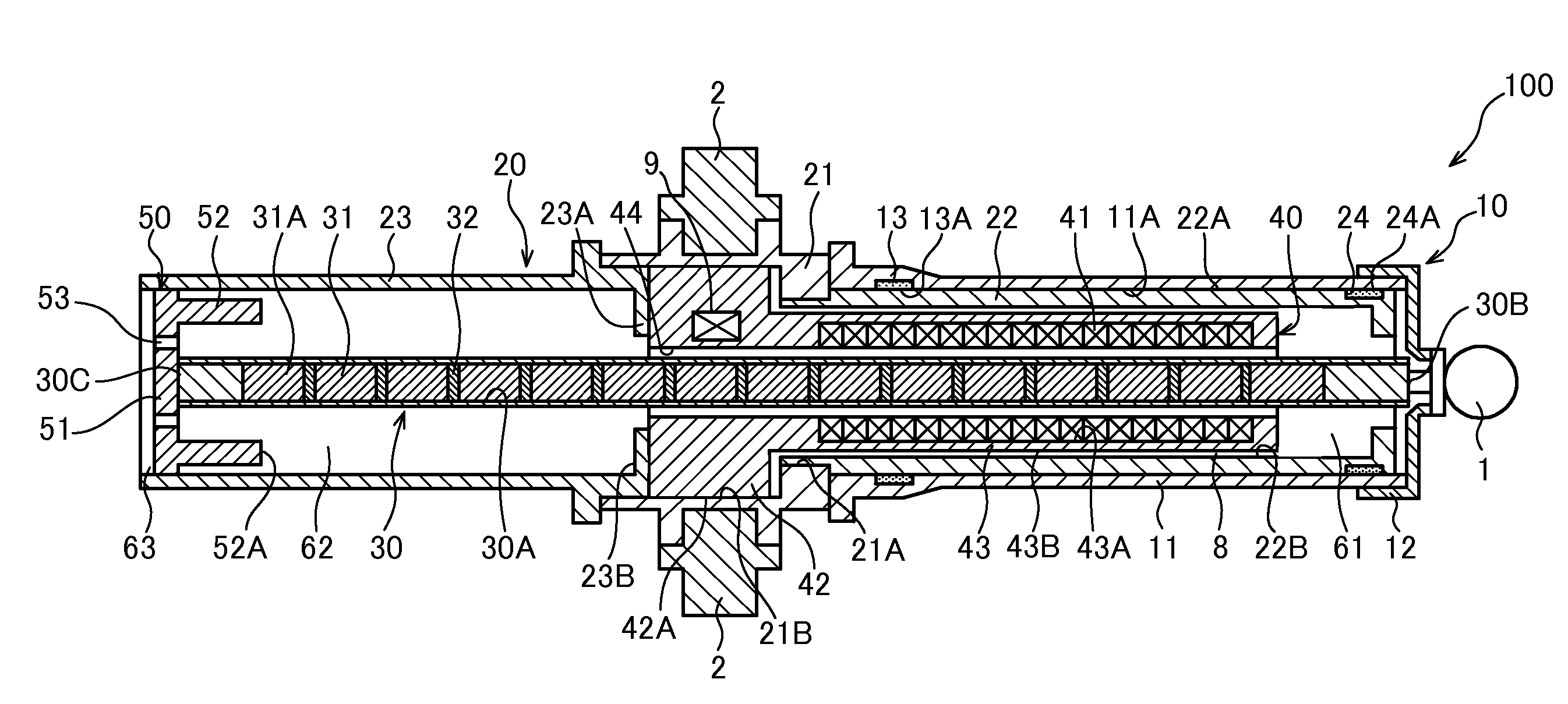
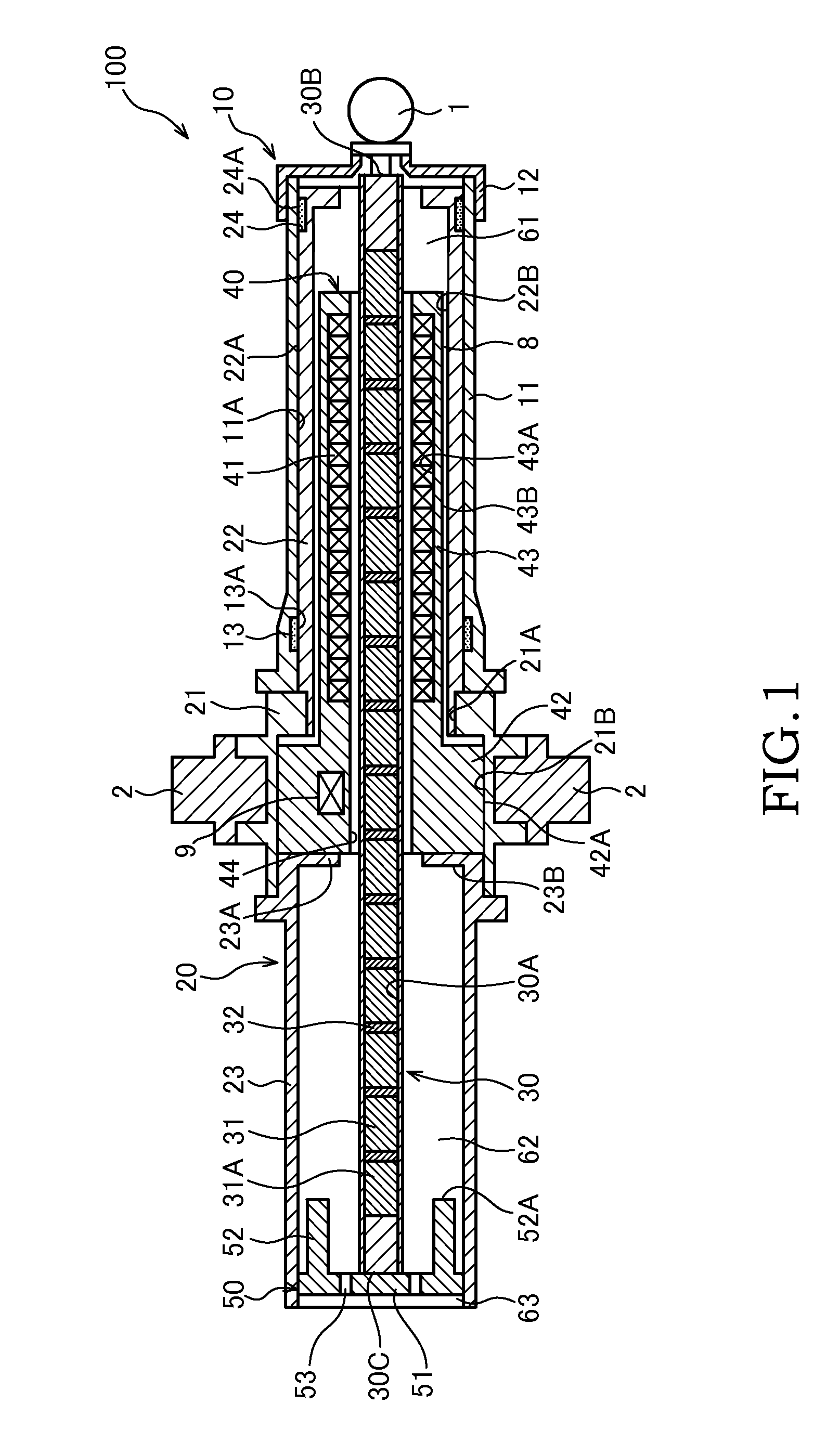
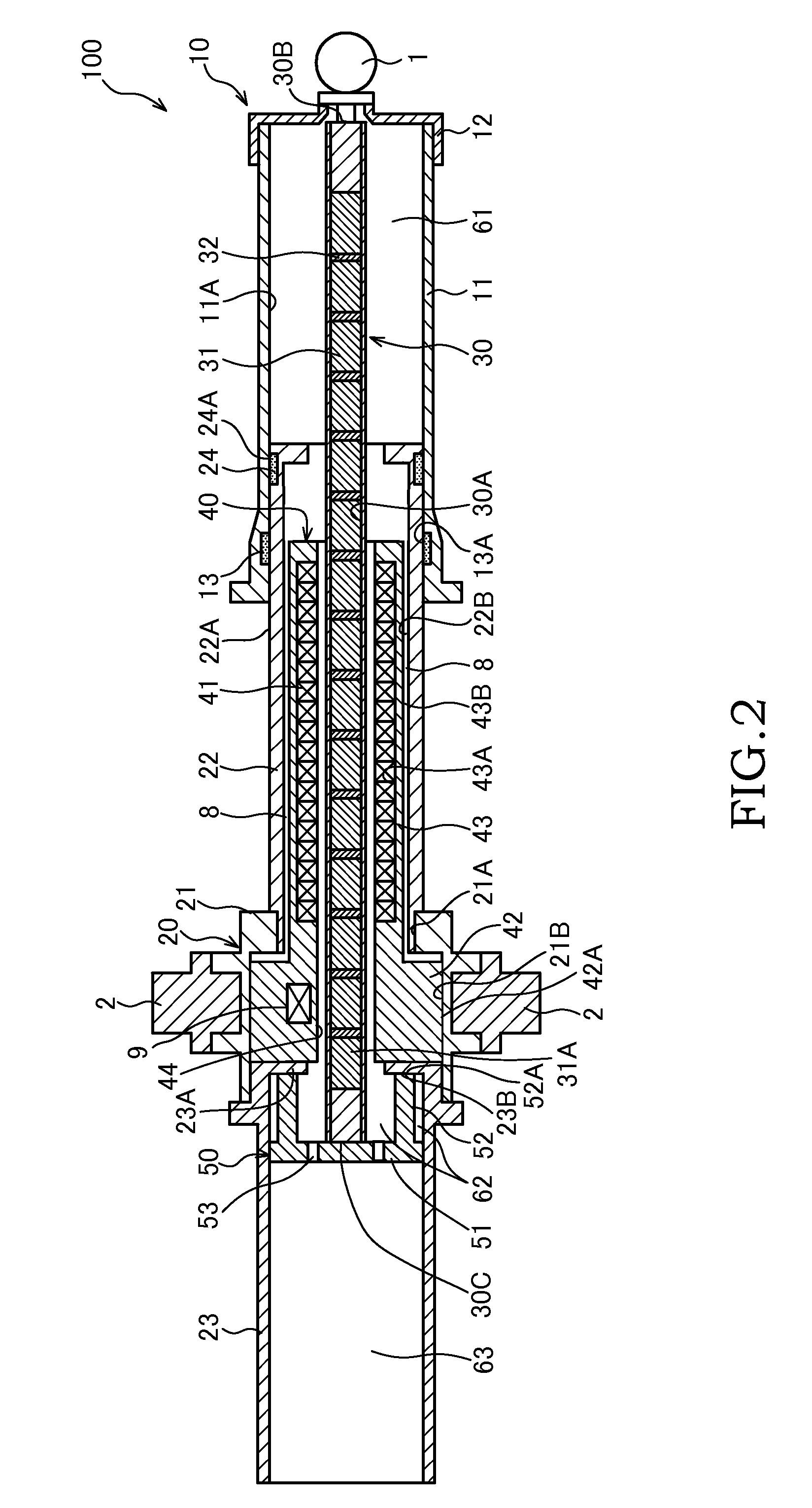
[0008]A linear actuator 100 according to an embodiment of the present invention will be described with reference to FIGS. 1 and 2.

[0009]The linear actuator 100 is used as a vibration control actuator for suppressing vibration in, for example, automobiles, railroad vehicles, buildings, and so forth.

[0010]The linear actuator 100 includes a first tube 10, a second tube 20 that is slidably inserted into the first tube 10, a rod 30 that is fixed at the end portion of the first tube 10 and that holds permanent magnets 31, and a coil holder 40 that is provided so as to be fitted with the inside of the second tube 20 and that holds coils 41 facing the permanent magnets 31. The linear actuator 100 is disposed between two members, which are relatively moved to each other, via a connecting portion 1 provided on the first tube 10 and connecting shafts 2 provided on the second tube 20.

[0011]In the linear actuator 100, a thrust (electromagnetic force) that drives the rod 30 in the axial direction...


PUM


Abstract

A linear actuator that is configured to be extended/contracted by relatively displacing a first tube and a second tube in an axial direction, includes a rod that is provided inside the first tube, a plurality of permanent magnets that are held in the rod so as to be arranged in the axial direction; a stopper that is provided on a tip-end portion of the rod, a coil that is provided inside the second tube so as to face the permanent magnets, and a stopper receiving portion that is provided on the second tube so as to face the stopper, wherein the relative displacement between the first tube and the second tube in the extension direction is restricted by bringing an extension-direction-side end surface of the stopper into contact with the stopper receiving portion at a fully extended position.

Description

TECHNICAL FIELD[0001]The present invention relates to a linear actuator that is extended / contracted in the axial direction by an electromagnetic force.BACKGROUND ART[0002]JP2005-106242A discloses a linear actuator in which a first tube and a second tube are relatively displaced in the axial direction by an electromagnetic force generated between permanent magnets provided in the first tube and coils provided in the second tube.SUMMARY OF INVENTION[0003]The linear actuator described in JP2005-106242A includes a shaft with fixed permanent magnets, and in a fully extended state, the shaft is subjected to a compression load due to self thrust. Therefore, the distortion of the shaft is easily propagated to the permanent magnets, and the permanent magnets may be damaged.[0004]An object of the present invention is to prevent a permanent magnet from being damaged due to self thrust in a linear actuator that is in a fully extended state.[0005]According to one aspect of the present invention,...

Claims


Application Information

Patent Timeline
Patent Type & Authority Applications(United States)
IPC IPC(8): H02K33/00
CPCH02K33/00H02K41/031H02K7/08H02K7/102
Inventor SATOU, KOUSUKETAKAHASHI, NORIYUKI
Owner KYB CORP
Why Eureka
Try Eureka