
Panel connector

a panel connector and connector technology, applied in the field of panel connectors, can solve the problems of affecting the integrity of the seal between the panel connector and the panel, affecting the connection, and affecting the connection, etc., and achieves the effect of simple locking mechanism, effective and robust sealing, and simple locking mechanism

Active Publication Date: 2015-01-08
MOLEX INC
View PDF8 Cites 10 Cited by
  • Summary
  • Abstract
  • Description
  • Claims
  • Application Information

AI Technical Summary

Benefits of technology

The present patent concerns a panel connector that can be easily installed and provides a tight seal. The connector has a locking mechanism that prevents the connector from being unlocked or disengaged from the panel. The connector can be securely locked onto the panel using a simple inserting process, where the connector locks onto the panel's outer surface. The flange of the connector sits between the insertion portion and the wall of the panel, with a gap in between, which allows for secure locking of the connector to the panel using the engagement lip. The sealing gasket in the connector's channel squeezes the panel's annular rib and inner wall, creating a tight seal. The locking member prevents the connector from being easily removed or rotated. Overall, this patent introduces a simple and effective way to connect panels in an outside-in installation.

Problems solved by technology

These two-part connectors typically require access to both sides of the panel, which may be difficult especially in the case of cramped enclosures or other module areas.
With inside-out installations for connectors having an end passing through the panel opening and extending towards the outer area for mating with a push-in or plug-in type connector, pushing against the panel connector from the outer area can cause the panel connector to be pushed out of engagement with the panel and / or can diminish the integrity of the seal between the panel connector and the panel.
Inside-out installation also tends to be difficult and / or time consuming mostly due to the tight spaces involved.

Method used


Image

  • Panel connector
  • Panel connector
  • Panel connector

Examples


Embodiment Construction

[0024]The detailed embodiments disclosed herein are merely exemplary of the inventions disclosed herein, which may be embodied in various forms, and specific details disclosed herein are not to be interpreted as limiting, but merely as a basis for the claims and as a representative basis for teaching one skilled in the art to variously employ the present approach in virtually any appropriate manner.

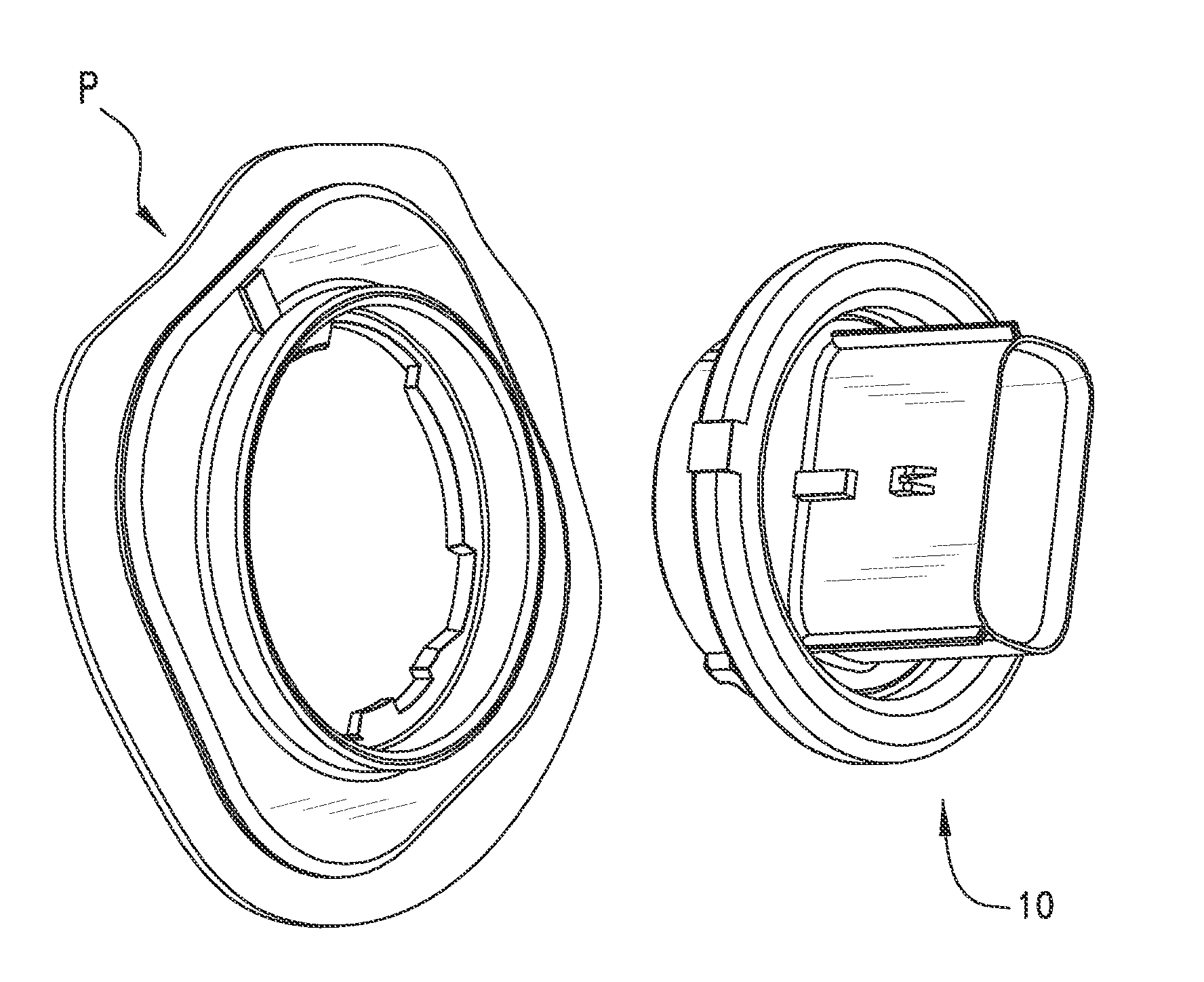
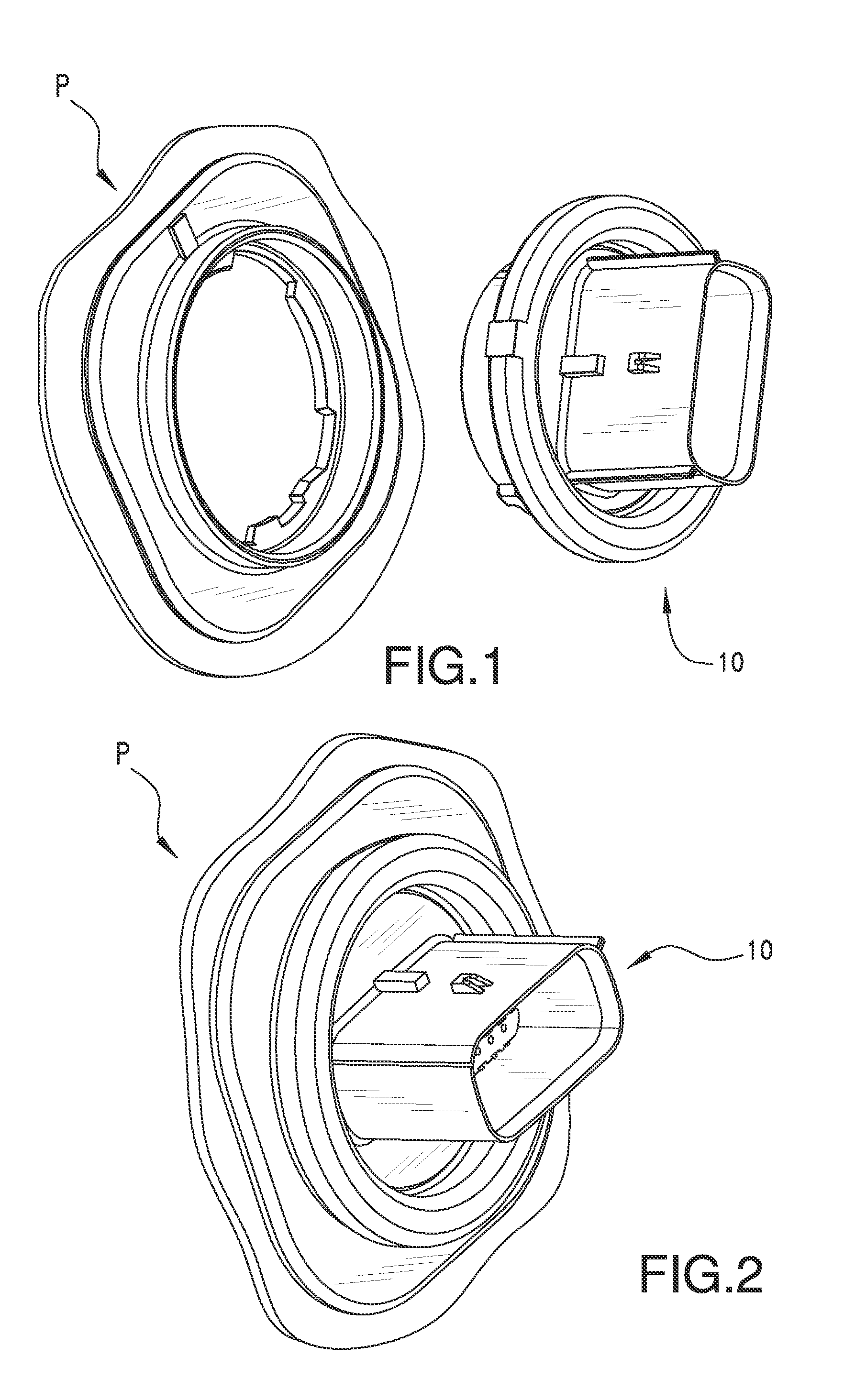
[0025]FIGS. 1 and 2 show one embodiment of a panel connector 10 disengaged and engaged to a panel “P”, respectively. Panel “P” can be part of a wall of an enclosure as shown in FIG. 3 or a wall separating two compartments (not shown). The connector 10 can include features which interact or cooperate with complementary features of panel “P”. The features of the panel which cooperate with connector 10 to providing locking, sealing and / or removal prevention can be included as part of the panel or can be included on a separate panel opening adapter which can mount to a typical pass through ho...


PUM


Abstract

The disclosure relates to a panel connector for locking to a pass-through opening of a panel to allow electrical connection from one side of the panel to the other side. This connection can be considered to be of an outside-in type. The connector can seal the pass-through opening to resist passage dirt, debris and / or liquids. A channel provided on the connector can include a sealing gasket and can receive an annular rib disposed on the panel to create an effective and robust seal against even pressurized water spray. The connector can also prevent unlocking of the connector from the panel once locked to the panel. A resilient locking arm provided on the connector for engaging a mating slot of the panel opening can prevent counter rotational unlocking and detent member can prevent continued rotation after the connector is in the locked position.

Description

RELATED APPLICATIONS[0001]This application claims priority to U.S. Provisional Application Ser. No. 61 / 605,281, filed Mar. 1, 2012, which is incorporated herein by reference in its entirety.TECHNICAL FIELD[0002]The present disclosure relates to electrical connectors and in particular, to bulkhead, panel or feed-through connectors for electrical use. In particular, the panel connectors disclosed herein can seal against the panel to provide some measure of water and weather resistance. More particularly, the disclosure is directed to panel connectors that can be sealingly locked to the panel by twisting or rotation of the connector and that can be locked to the panel from the outside. Even more particularly, the disclosure is directed to panel connectors that cannot be unlocked once locked to the panel.BACKGROUND ART[0003]Panel electrical connectors are typically used to provide electrical connections through a pass-through or feed-through hole from one side of a bulkhead, wall or pan...

Claims


Application Information

Patent Timeline
Patent Type & Authority Applications(United States)
IPC IPC(8): H01R13/52H01R4/12H01R13/627
CPCH01R13/521H01R4/12H01R13/6272H01R13/5202H01R13/743
Inventor VANSLAMBROUCK, MIKEMAUNEY, JOEKOSHY, VIJY
Owner MOLEX INC
Learn More