
Structure for guiding light into guide light plate to conduct total internal reflection

a technology of guide light and internal reflection, which is applied in the direction of instruments, lighting and heating apparatus, mechanical apparatus, etc., can solve the problems of inability to meet the requirements of lightness, thinness, shortness and smallness, and the light source shoots the light into the optical coupler, etc., to achieve the effect of reducing the thickness of the prism, small size and low efficiency

Inactive Publication Date: 2015-01-08
ERA OPTOELECTRONICS
View PDF10 Cites 49 Cited by
  • Summary
  • Abstract
  • Description
  • Claims
  • Application Information

AI Technical Summary

Benefits of technology

This patent describes a structure for guiding light into a device to conduct total internal reflection. The special configuration of the prism and the arrangement between the guide light plate and the prism allow most of the light to be directed into the device and propagate the total internal reflection with high intensity even if the light source is not very efficient. Additionally, the prism is designed with a reduced thickness of only 20 degrees, which makes it thinner and more suitable for electronic products that require lightweight, thin, and small dimensions.

Problems solved by technology

But various types of optical couplers taught in US Patent Publication No. 20130021302 are huge in sizes which increase the weight and volume of the electronic product such that it is incapable of meeting requirements of lightness, thinness, shortness and smallness for the electronic product; in addition, the angle with which the light source shoots the light into the optical coupler is restricted as well, that is, it is incapable for the light to shoot into the optical coupler with any angle in order to be guided into the guide light plate by the coupler to perform the total internal reflective propagation.

Method used


Image

  • Structure for guiding light into guide light plate to conduct total internal reflection
  • Structure for guiding light into guide light plate to conduct total internal reflection

Examples


Embodiment Construction

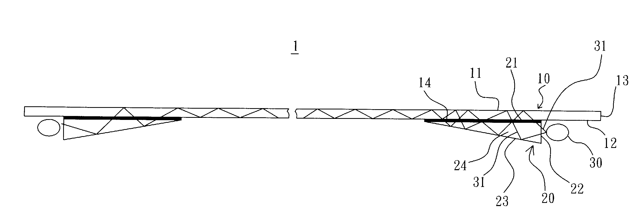
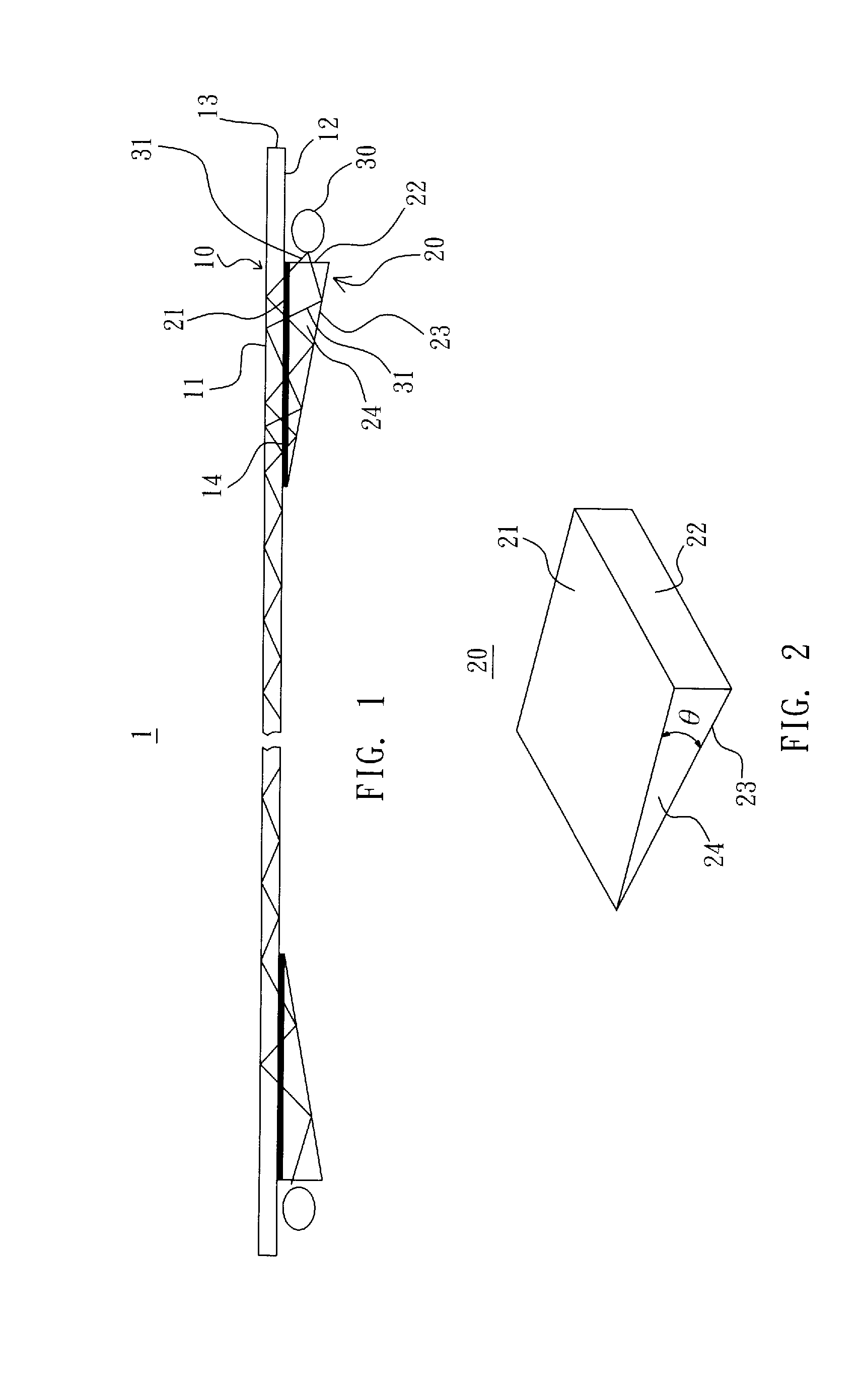
[0017]Referring to FIG. 1, a structure 1 for light guided into a light guide plate to conduct total internal reflection in accordance with the present invention comprises a guide light plate 10 and a prism 20.

[0018]The guide light plate 10 has an upper surface 11 and a lower surface 12 which are parallel with each other, and a peripheral surface 13 is formed by lateral edges of the guide light plate 10. The guide light plate 10 is made of guide light material such as acrylic, resin or glass in a form of bendable or unbendable plate.

[0019]The prism 20 has a horizontal surface 21, a vertical surface 22, a slant surface 23, and two opposite side surfaces 24. The horizontal surface 21 has two ends connecting with the vertical surface 22 and the slant surface 23, respectively. The two side surfaces 24 connect with the horizontal surface 21, the vertical service 22, and the slant surface 23, respectively. The horizontal surface 21 is perpendicular to the vertical surface 22. An angle θ be...


PUM


Abstract

A structure for guiding light into a light guide plate to conduct total internal reflection comprises a guide light plate and a prism; the prism is integrated with the guide light plate or joined to the guide light plate with an optical adhesive layer; the horizontal surface of the prism is parallel to the upper and lower surfaces of the guide light plate; the maximum angle between the horizontal surface and the slant surface of the prism is only 20 degrees to reduce the thickness of the prism greatly to meet requirements of lightness, thinness, shortness, and smallness for the electronic product; due to a special configuration of the prism and a special arrangement between the guide light plate and the prism, the most part of the light shot to the prism by the light source with any projecting angle is guided into the guide light plate to propagate the total internal reflection such that the light has an intensity capable of being sensed.

Description

CROSS-REFERENCE TO RELATED APPLICATIONS[0001]The application claims priority from Taiwan Patent Application No. 102123951 filed on Jul. 4, 2013, the disclosure of which is incorporated herein by reference.BACKGROUND OF THE INVENTION[0002]1. Field of the Invention[0003]The present invention relates to a touch device with a guide light plate, and, more particularly, to a structure for guiding light into a guide light plate to conduct total internal reflection.[0004]2. Description of Related Art[0005]Many touch devices are employed to join with guide light plates. For instance, U.S. Pat. No. 7,432,893B2 which discloses an input device based on frustrated total internal reflection in which lights emitting from two or more light sources are shot into a transparent plate to conduct total internal reflection and sensed by a light sensing array which is disposed opposite to the light sources and surround the peripheral side of the transparent; when an object touches the surface of the trans...

Claims


Application Information

Patent Timeline
IPC IPC(8): F21V8/00
CPCG02B6/0031G02B6/0028G02B6/421G02B6/4214G06F3/0421
Inventor LIN, CHIH-HSIUNG
Owner ERA OPTOELECTRONICS
Learn More