Bicycle control system
a control system and bicycle technology, applied in electric controllers, ignition automatic control, instruments, etc., can solve the problems of laborious maintenance of power supplies, and achieve the effects of reducing labor for replacing or charging batteries, and improving flexibility of arrangemen
- Summary
- Abstract
- Description
- Claims
- Application Information
AI Technical Summary
Benefits of technology
Problems solved by technology
Method used
Image


Examples
first embodiment
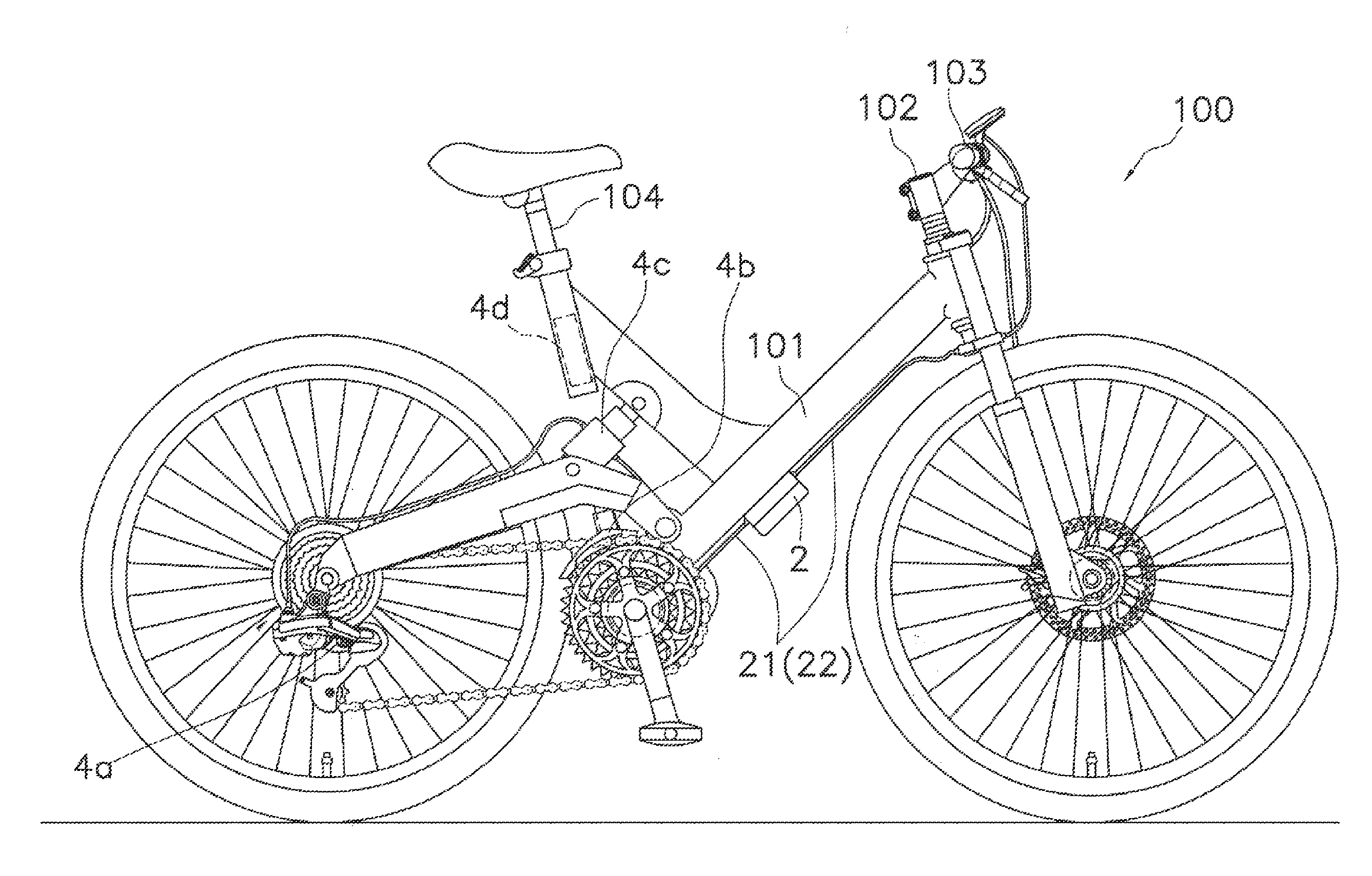
[0042]91 As shown in FIG. 1, a bicycle 100 to which a bicycle control system I according to a first embodiment is applied has a frame main body 101, a stem (one example of the movable member) 102, a handlebar (one example of the movable member) 103, and a seat post 104.
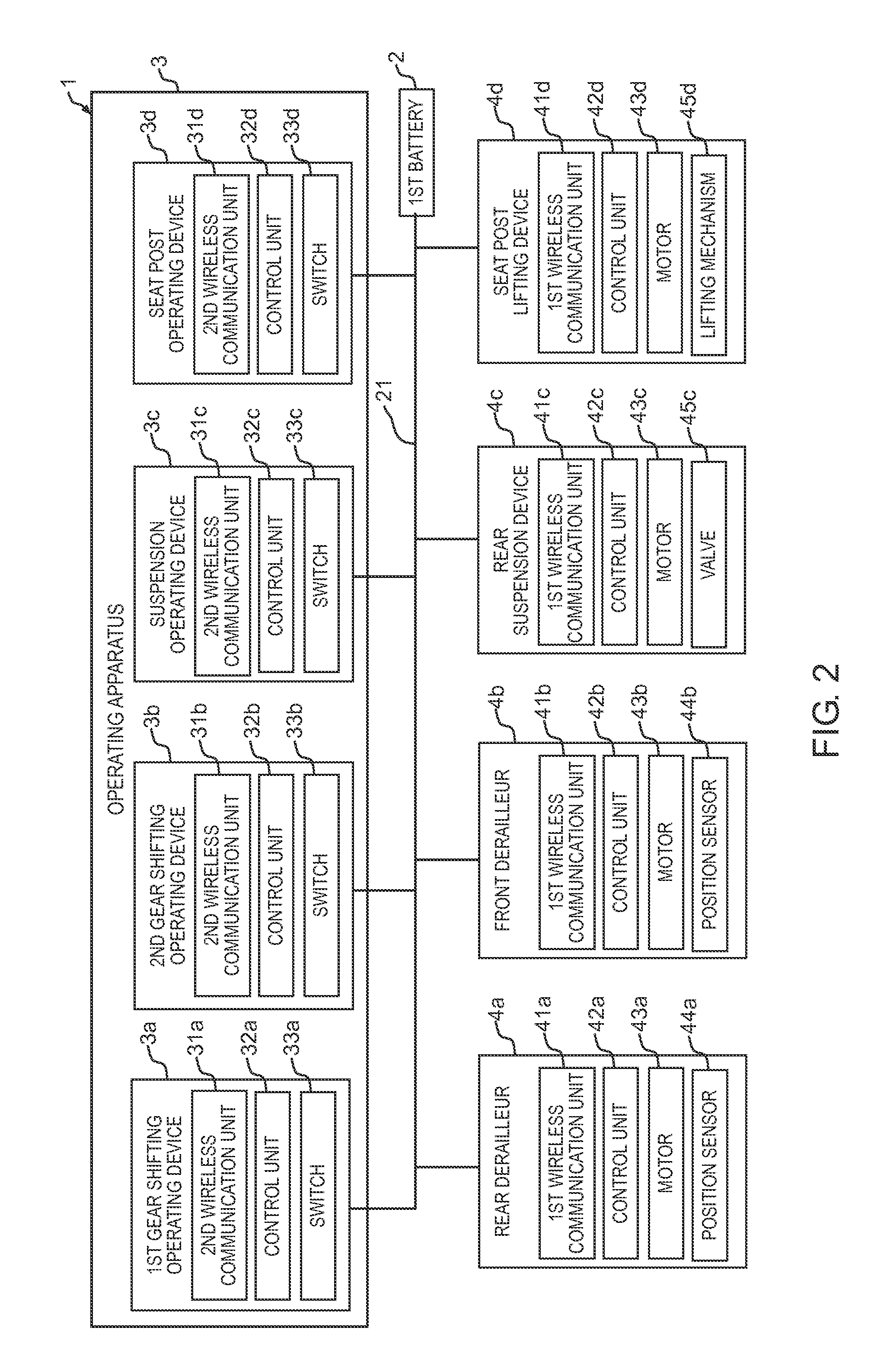
[0043]401 As shown in FIG. 2, the bicycle control system 1 has a first battery (one example of the first power supply) 2, an operating apparatus 3, and a plurality of electric drive devices 4a - 4d. The plurality of electric drive devices 4a - 4d are, for example, a rear derailleur (one example of the rear transmission device) 4a, a front derailleur (one example of the front transmission device) 4b, a rear suspension device 4c, and a seat post lifting device 4d. Each of the electric drive devices 4a - 4d is attached to the frame main body 101.
[0044]411 The plurality of electric drive devices 4a - 4d have first wireless communication unit s 41a-41d, respectively. Specifically, the rear derailleur 4a has the first wirel...
second embodiment
[0056]As shown in FIG. 3, a bicycle control system 10 according to a second embodiment is different from the bicycle control system 1 according to the above-described first embodiment in that the bicycle control system 10 further comprises a second battery (one example of the second power supply) 5. The configuration other than the presence of the second battery 5 is basically the same as in the bicycle control system 1 according to the above-described first embodiment. Therefore, the same reference numerals are assigned to the parts that are configured in the substantially same manner, and overlapping explanations are omitted.
[0057]The second battery 5 is provided as a separate member from the operating devices 3a-3d. The second battery 5 is connected to the operating devices 3a-3d, and supplies electric power to the operating devices 3a-3d in a wired manner. The second battery 5 is connected to the operating devices 3a-3d through an electric power line 23. For example, the electri...
third embodiment
[0058]551 As shown in FIG. 4, a bicycle control system 11 according to a third embodiment is different from the bicycle control system 1 according to the first embodiment in that the bicycle control system 11 further comprises the second battery 5 and the electric drive devices 4a-4d share a single first wireless communication unit 41. The configuration other than these differences is basically the same as in the bicycle control system 1 according to the above-described first embodiment. Therefore, the same reference numerals are assigned to the parts that are configured in the substantially same manner, and overlapping explanations are omitted. Also, the configuration of the second battery 5 is basically the same as in the bicycle control system 10 according to the above-described second embodiment. Therefore, the same reference numerals are assigned to the parts that are configured in the substantially same manner, and overlapping explanations are omitted.
[0059]In the bicycle cont...
PUM
 Abstract
Description
Claims
Application Information
 - R&D
- Intellectual Property
- Life Sciences
- Materials
- Tech Scout
- Unparalleled Data Quality
- Higher Quality Content
- 60% Fewer Hallucinations
Browse by: Latest US Patents, China's latest patents, Technical Efficacy Thesaurus, Application Domain, Technology Topic, Popular Technical Reports.
© 2025 PatSnap. All rights reserved.Legal|Privacy policy|Modern Slavery Act Transparency Statement|Sitemap|About US| Contact US: help@patsnap.com