
Device having a measuring apparatus for measuring forces and/or loads

Active Publication Date: 2015-01-01
ZF FRIEDRICHSHAFEN AG
View PDF5 Cites 7 Cited by
  • Summary
  • Abstract
  • Description
  • Claims
  • Application Information

AI Technical Summary

Benefits of technology

The present invention aims to provide a component of a device that can be easily and inexpensively designed in relation to the measuring fixture used. It uses a field-generating means and a detection means that can detect changes in an alternating electromagnetic field caused by mechanical loads acting on the component. This detection method is insensitive to interfering fields and does not damage other electronic systems in the device. The field-generating means and detection means are held fixed in a housing to prevent displacement, which could affect the measurement. The detection means can be arranged at a distance from the chassis component to avoid interference from the environment. These features make the design simple, cost-effective, and reliable.

Problems solved by technology

This has the disadvantage that a material specially suited to and prepared for this application has to be used, which material itself constitutes the component to be measured or is worked into the component as a supplementary material.
A special magnetic coding of the material is very costly and makes it impossible to use the measurement process—having regard to the nature of the material—on any arbitrary materials.
Moreover, a further difficulty of magnetic coding is that its long-term stability is hard or even impossible to ensure.
Another disadvantage consists in that the detection and evaluation of a static magnetic field is sensitive to interfering fields in the surroundings, and conversely, so that in the automotive sector manufacturers prescribe the avoidance of static magnetic fields.

Method used


Image

  • Device having a measuring apparatus for measuring forces and/or loads
  • Device having a measuring apparatus for measuring forces and/or loads
  • Device having a measuring apparatus for measuring forces and/or loads

Examples


Embodiment Construction

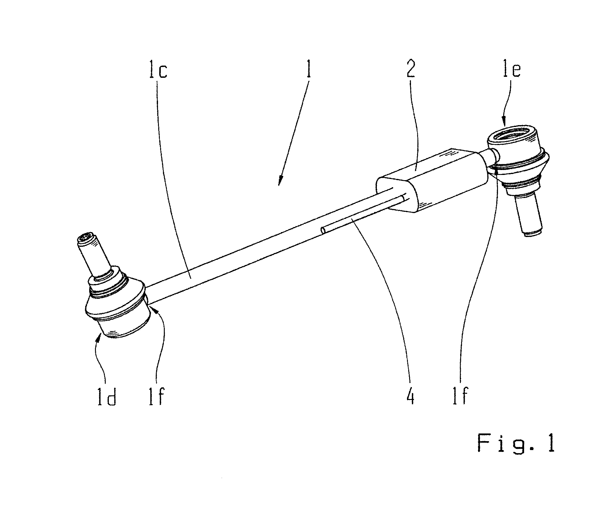
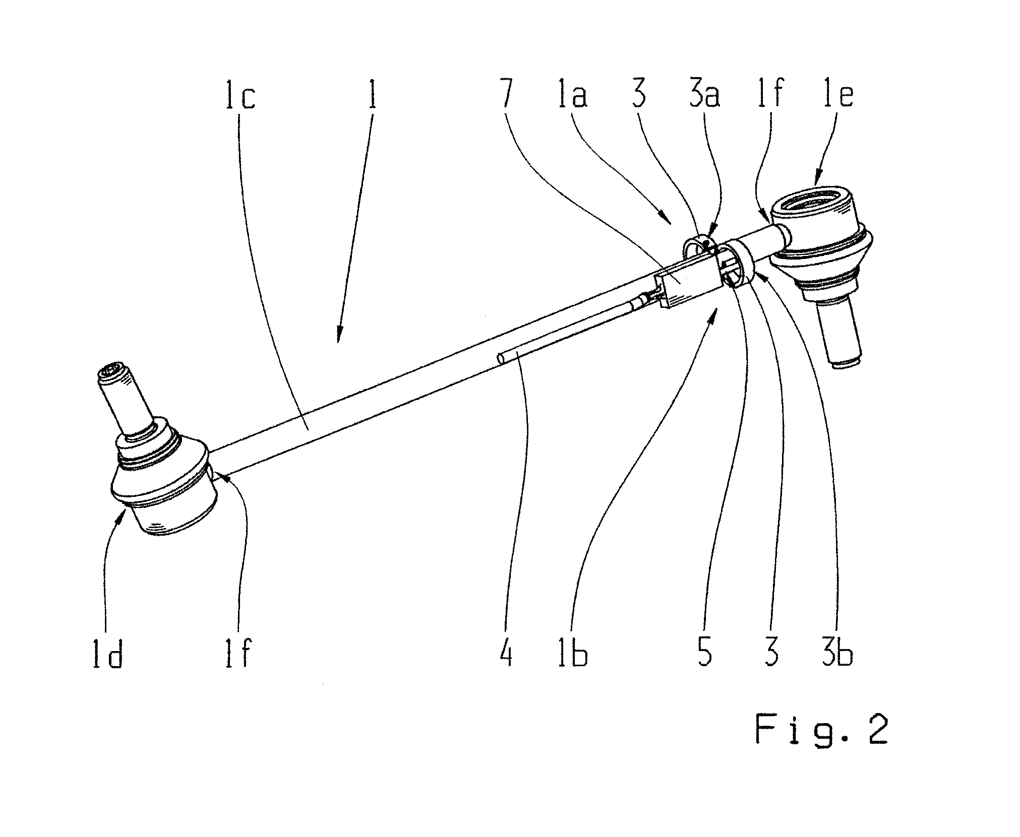
[0063]FIG. 1 shows a chassis component 1 according to the invention, which is in the form of a connecting strut 1c, for example a hinged support, and which has at its ends ball bearings 1d, 1e or corresponding bearing sleeves. At the points indexed 1f the connecting strut 1c is joined to the ball bearings 1d, 1e in a material-cohesive manner by means of a weld seam, although this cannot be explicitly seen in the figures. On the chassis component 1 is arranged a housing 2, preferably made of plastic. In the housing 2 is arranged, in the manner described in the introduction and in the annex, a measuring fixture (not visible in FIG. 1), which will be described in more detail below with reference to the other figures. The housing 2 protects the parts of the measuring fixture and secures them in position relative to the connecting strut 1c and the component 1. Cables 4 emerge from the housing 2 to carry the measurement signals emitted. The cable connections lead, for example, to the cont...


PUM


Abstract

A component of a machine. The component has a measuring fixture for measuring forces and at least one metallic, magnetic portion. The measuring fixture includes at least one field-generating member for producing an electromagnetic alternating field and at least one detection member for detecting changes of the magnetic field produced. The field-generating member and the detection members are arranged on the metallic, magnetic portion and are designed to interact with the metallic, magnetic portion in such manner that by way of the measuring fixture, as a function of measurement signals from the detection member, forces acting on and / or deformations of the component can be detected.

Description

[0001]This application is a National Stage completion of PCT / EP2012 / 073053 filed Nov. 20, 2012, which claims priority from German patent application serial no. 10 2011 089 605.8 filed Dec. 22, 2011.FIELD OF THE INVENTION[0002]The present invention concerns a component of a device, for example a chassis component of a (motor)-vehicle or a rotor component of a wind power generator, which component comprises a measuring fixture for the measurement of forces, and at least one metallic, magnetic portion as described below. Furthermore, the present invention concerns a driver assistance system for a motor vehicle, as described below, as well as a diagnosis system for a device, preferably a vehicle, as described below,BACKGROUND OF THE INVENTION[0003]Manufacturers generally strive to provide components with as long a useful life as possible and which at the same time are simple and inexpensive to produce. To that end measurement concepts are (further) developed, by means of which the loads...

Claims


Application Information

Patent Timeline
IPC IPC(8): G01L1/12F03D11/00B60T8/17
CPCG01L1/12B60T8/17F03D11/0091B60G2206/11B60G2204/1162B60G2401/17B60G2600/22B60G2400/94G01L1/127B60G7/001B60G17/019F03D17/00
Inventor HOFMANN, PETERNACHBAR, FRANKHAEVESCHER, RAINER
Owner ZF FRIEDRICHSHAFEN AG
Learn More