Injection molding module and injection molding method utilizing the same

a technology of injection molding module and injection molding method, which is applied in the field of injection molding module, can solve the problems of mist-like defects, molded products cannot meet the consumer's requirements for brightness and smoothness, and the appearance of molded products is damaged, etc., and achieves the effect of increasing temperature, and destroying the directionality of the flow of plastic materials

Inactive Publication Date: 2015-01-01
WISTRON CORP
View PDF3 Cites 2 Cited by
  • Summary
  • Abstract
  • Description
  • Claims
  • Application Information

AI Technical Summary

Benefits of technology

[0015]The effects achievable by the disclosure reside in the following. By virtue of the inlet having an axial direction that is not parallel with the lengthwise direction of the main section of the cooling runner, the plastic material has a flow direction that is changed when the plastic material is fed into the cooling runner through the inlet so as to destroy the directionality of the plastic material flow. By virtue of the design of the tapering section, the plastic material forms two portions having different flow directions before entering the cavity and the two portions are mixed with each other and have an increased temperature, thereby again destroying the directionality of the flow of the plastic material and avoiding the damage to the inner surface of the mold unit of the injection molding module otherwise caused by the plastic material if the same flows from the inlet into the outlet along a single direction. Besides, since the outlet of the cooling runner is in spacial communication with the second portion for molding the side wall of the molded product, the residual plastic material is connected to the second portion of the cavity that has a relatively low brightness requirement. Additionally, the area of the molded product connected to the residual plastic material is also reduced by means of the tapering section and thus, the residual plastic material connected to the molded product can be easily broken off and additional cost and time required for the process of removing the residual plastic material, such as computer numeric control (CNC) processing, numeric control (NC) processing or manual cutting processing, can be omitted.

Problems solved by technology

However, addition of the fiber components into the plastic material during the injection molding operation as mentioned above tends to create a new problem that is not encountered when the plastic material is free of fiber components.
Consequently, the inner surface of the female mold 12 is unavoidably scratched by the plastic material, which leads to damaged appearance of the molded product, e.g., having mist-like defects.
Such molded products cannot meet the consumers' requirements for brightness and smoothness.
In addition, once the inner surface of the female mold 12 is damaged, the entire injection molding process will be forced to shut down for repairing the conventional injection molding module 1.
Hence, not only are extra time and manpower needed, but the shutdown of the production lines also results in a reduction in productivity.
After the molded product is cooled down and shaped, a residue of the plastic material left in the cooling runner 14 is connected to the molded product and needs to be removed, increasing both the production cost and time.

Method used


Image

  • Injection molding module and injection molding method utilizing the same
  • Injection molding module and injection molding method utilizing the same
  • Injection molding module and injection molding method utilizing the same

Examples


Embodiment Construction

[0020]Before the present disclosure is described in greater detail with reference to the accompanying embodiments, it should be noted herein that like elements are denoted by the same reference numerals throughout the disclosure.

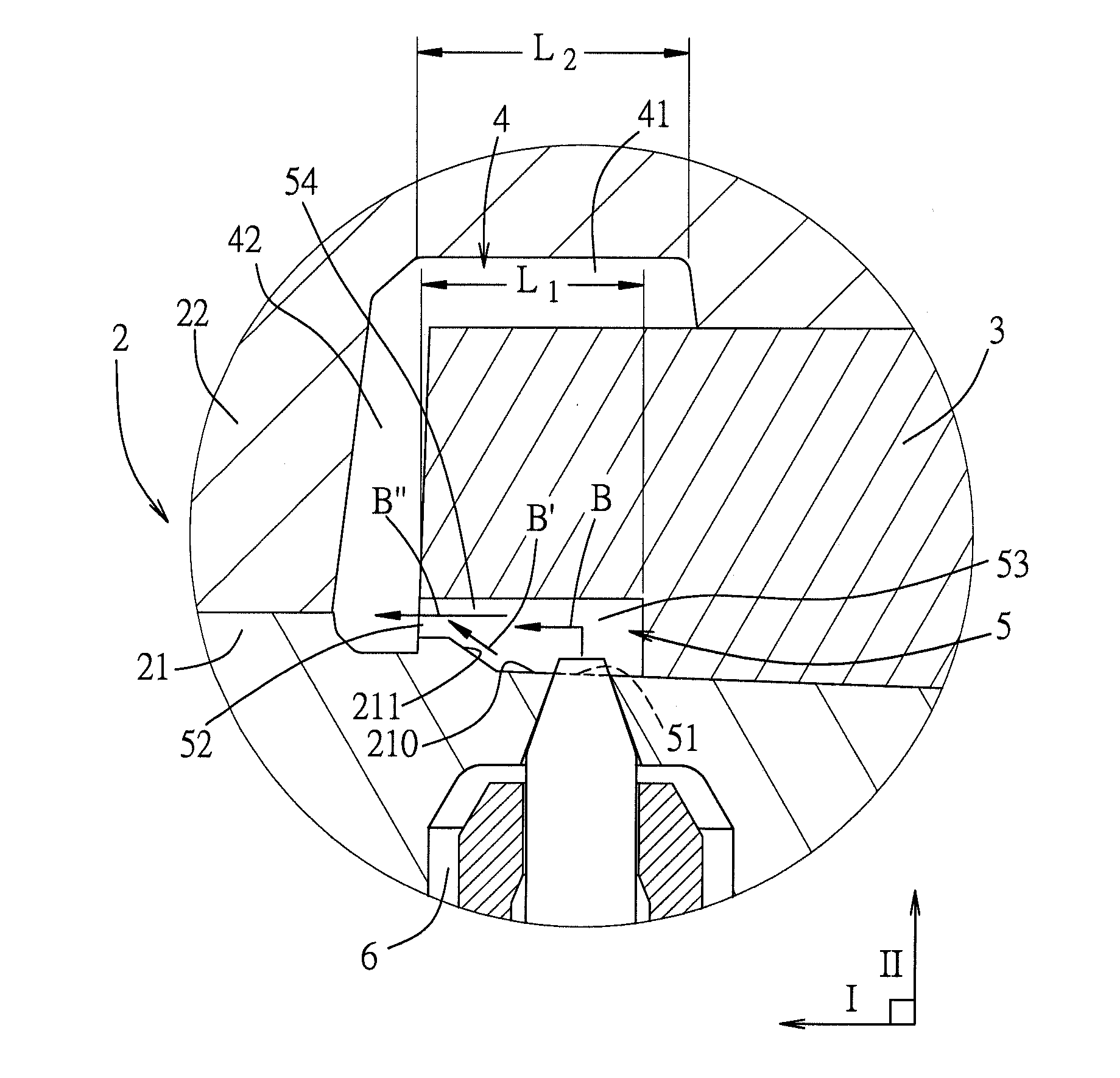
[0021]Referring to FIG. 2, the first embodiment of an injection molding module according to the present disclosure is illustrated. The injection molding module includes a mold unit 2, a slider 3 disposed in the mold unit 2, a cavity 4 and a cooling runner 5. The mold unit 2 includes a first mold 21 and a second mold 22. The first mold 21 and the second mold 22 cooperate with the slider 3 to define the cavity 4. The first mold 21 has an inner wall surface 210. The slider 3 cooperates with the inner wall surface 210 to define the cooling runner 5. The inner wall surface 210 includes an inclined region 211. The cavity 4 is used for forming a molded product and includes a first portion 41 for molding a main wall of the molded product and a second portion 42 that...


PUM

PropertyMeasurementUnit
included angleaaaaaaaaaa
areaaaaaaaaaaa
lengthaaaaaaaaaa

Abstract

The disclosure relates to an injection molding module including a mold unit and a slider that is disposed in the mold unit and that cooperates with the mold unit to define a cavity and a cooling runner in spacial communication with the cavity. The cooling runner includes a main section that is formed with an inlet, and a tapering section that extends from the main section in a lengthwise direction and that is formed with an outlet in spatial communication with the cavity. The inlet has an axial direction that is not parallel with the lengthwise direction, thereby the plastic material having a flow direction that is changed when a plastic material is fed into the cooling runner through the inlet.

Description

CROSS REFERENCE TO RELATED APPLICATION[0001]This application claims priority of Taiwanese application no. 102123283 filed on Jun. 28, 2013, the disclosure of which is incorporated herein by reference.BACKGROUND OF THE DISCLOSURE[0002]1. Field of the Disclosure[0003]The disclosure relates to an injection molding module, more particularly to an injection molding module that is able to prevent a fiber component that is present in a plastic material to be injection molded from damaging a surface of a molded product. The disclosure also relates to an injection molding method utilizing the injection molding module.[0004]2. Description of the Related Art[0005]In recent years, for the process of injection molding plastic materials, in order to enhance the rigidity, surface smoothness, brightness and other characteristics of the molded products to meet the consumers' demands, a great number of fiber components (such as glass fiber, carbon fiber, etc.) are added to the plastic material.[0006]...

Claims


Application Information

Patent Timeline
Patent Type & Authority Applications(United States)
IPC IPC(8): B29C45/27
CPCB29C45/2756B29C44/582B29C44/585B29C45/33B29C45/585
Inventor LIN, YUAN-SHIANGTSAI, CHIEN-HUNGHUNG, AN-CHEN
Owner WISTRON CORP
Why Eureka
Try Eureka