
Computer system and power management method thereof

a computer system and power management technology, applied in the field of electronic devices, can solve problems such as increased costs

Active Publication Date: 2014-12-25
QUANTA COMPUTER INC
View PDF11 Cites 8 Cited by
  • Summary
  • Abstract
  • Description
  • Claims
  • Application Information

AI Technical Summary

Benefits of technology

This patent describes a computer system and a power management method that can adjust the frequency of the CPU and GPU to save power. The system comprises a system load with a CPU, GPU, and embedded controller. The embedded controller determines the system power consumption and adjusts the frequency of the CPU and GPU to reduce power consumption. This can include activating or deactivating certain functions of the CPU and GPU. The method also includes a reverse adjustment sequence for the second and third frequencies, which will be useful for cooling the system. The technical effect is to improve the system's power management and cooling by adjusting the frequency of the CPU and GPU according to the system's power consumption.

Problems solved by technology

Such method, although being capable of preventing a power shutdown of a system load resulted by insufficient power, also leads to increased costs due to an excessive design of the power supply as the system load does not at all times operate at a full load.

Method used


Image

  • Computer system and power management method thereof
  • Computer system and power management method thereof
  • Computer system and power management method thereof

Examples


first embodiment

[0015]

TABLE 1Rated power ofFirst safe operating pointSecond safe operating pointAC adapter(rated power × 95%)(rated power × 90%)65 W61 W58 W90 W85 W81 W120 W 114 W 108 W 

TABLE 2FrequencyFrequency reductionFrequency reductionreduction modefunction of CPUfunction of GPUFirst frequencyDisableDisablereduction modeSecond frequencyDisableEnablereduction modeThird frequencyEnableEnablereduction mode

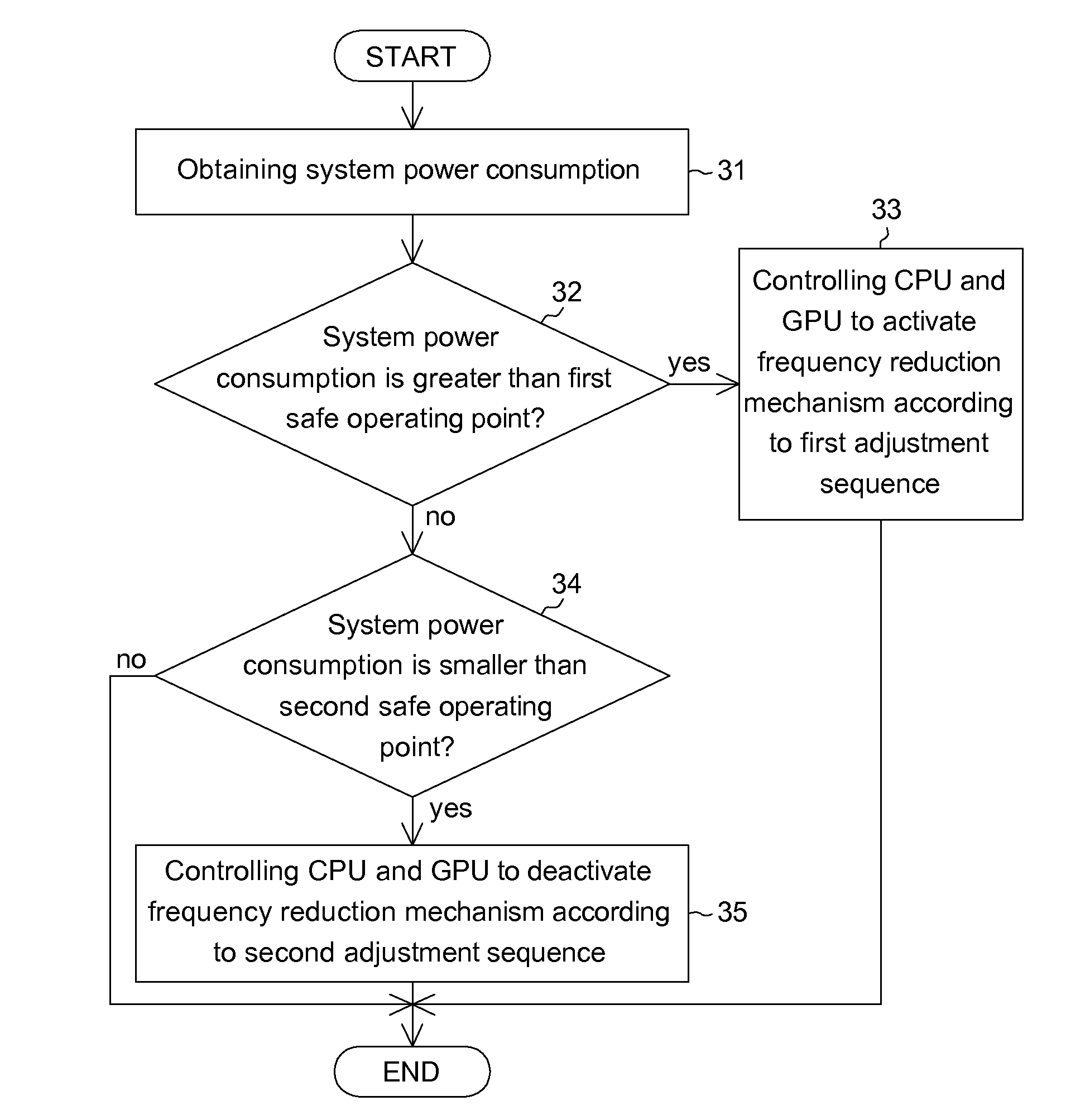
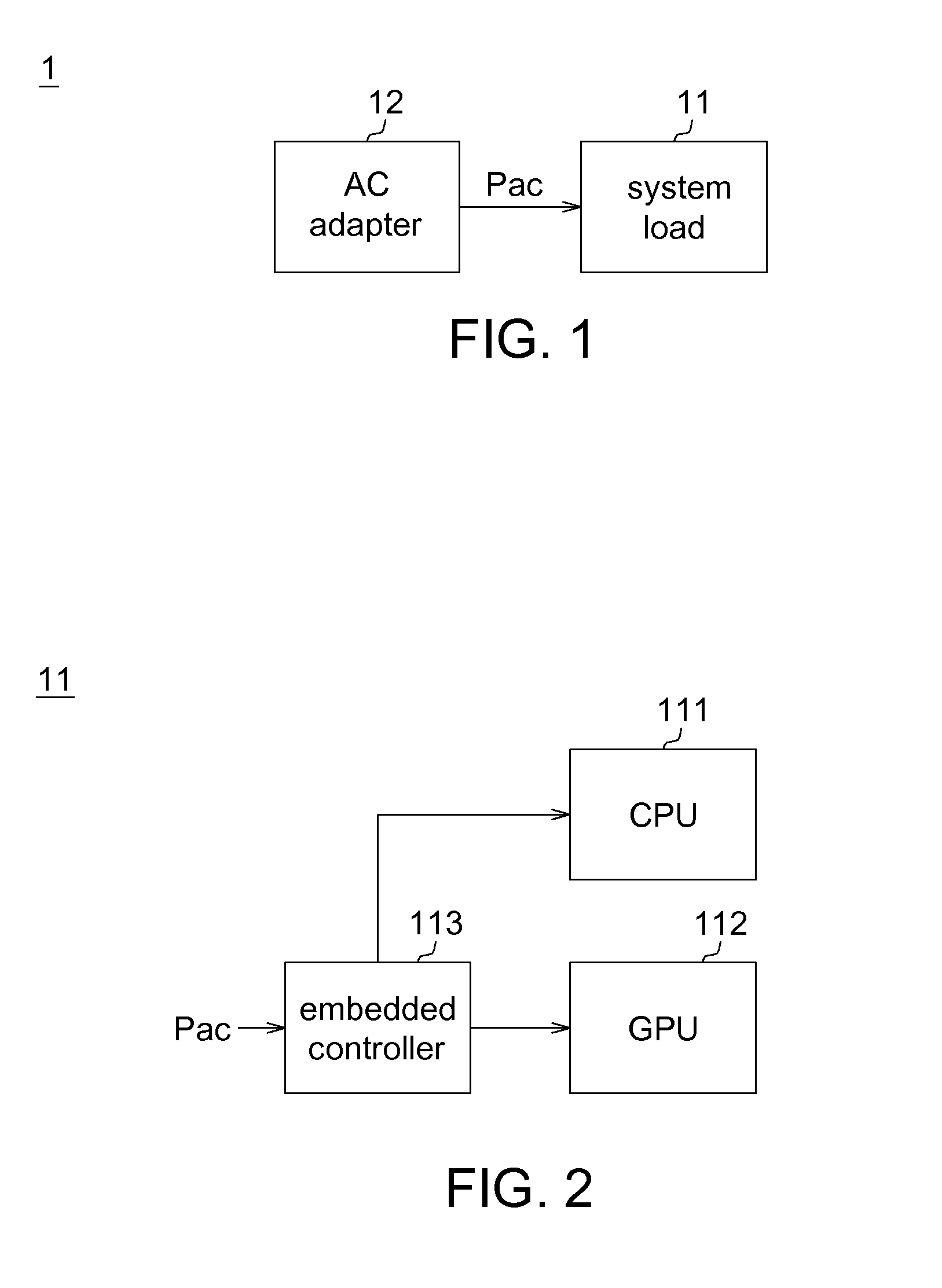
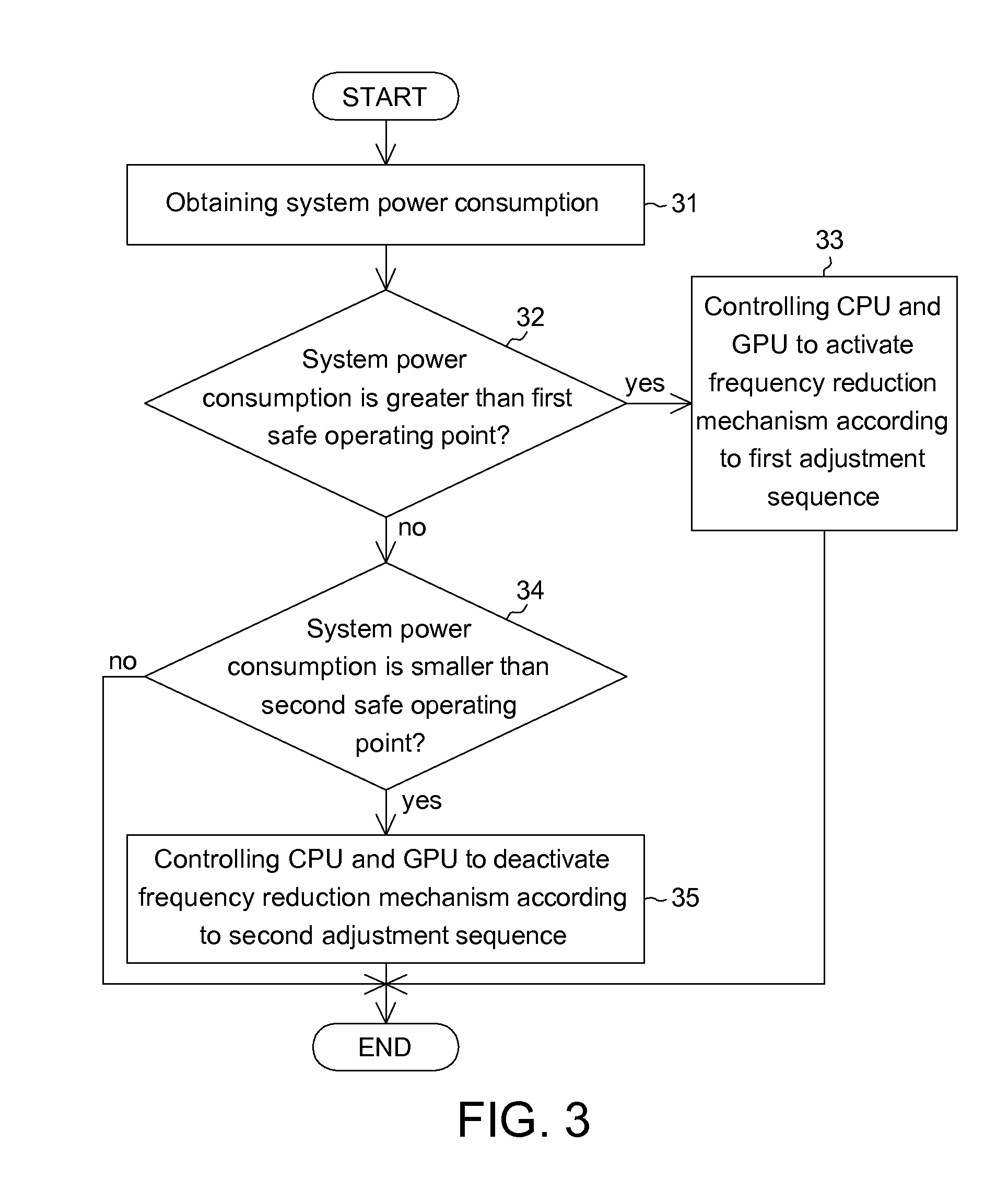
[0016]Table-1 records first safe operating points and second safe operating points corresponding to rated powers of different AC adapters. Table-2 records enable / disable states of a frequency reduction function of a CPU and a graphics processing unit (GPU) under different frequency reduction modes. FIG. 1 shows a schematic diagram of a computer system according to a first embodiment. FIG. 2 shows a partial schematic diagram of a system load according to the first embodiment. FIG. 3 shows a flowchart of a power management method for a computer system according to the first embodiment. Referring t...

second embodiment

[0024]

Total powerTotal powerVoltage Turboconsumption ≧ Systemconsumption Boost (VTB)rated powerrated powerEnablePowered by AC adapterPowered by AC adapter,and batterybattery being rechargedDisablePowered by only ACPowered by AC adapter,adapterbattery being recharged

[0025]Table-3 records power conditions of an AC adapter and a battery after enabling / disabling a voltage turbo boost function. FIG. 4 shows a schematic diagram of a computer system according to a second embodiment. FIG. 5 shows a partial schematic diagram of a system load according to the second embodiment. A main difference of the second embodiment from the first embodiment is that, a computer system 2 further comprises a battery 13 and a smart charger 14. The embedded controller 113 obtains a remaining power percentage Pc of the battery 13, and determines whether the remaining power percentage Pc is smaller than a threshold. An end voltage of the battery 13 lowers as the remaining power of the battery 13 reduces. To mai...


PUM


Abstract

A power management method for a computer system is provided. The power management method includes: obtaining a system power consumption; determining whether the system power consumption is greater than a first safe operating point; when the system power consumption is greater than the first safe operating point, controlling a CPU and a graphics processing unit (GPU) to activate a frequency reduction mechanism according to a first adjustment sequence; when the system power consumption is not greater than the first safe operating point, determining whether the system power consumption is smaller than a second safe operating point; and when the system power consumption is smaller than the second safe operating point, controlling the CPU and the GPU to deactivate the frequency reduction mechanism according to a second adjustment sequence. The second adjustment sequence is reverse to the first adjustment sequence.

Description

[0001]This application claims the benefit of Taiwan application Serial No. 102121956, filed Jun. 20, 2013, the subject matter of which is incorporated herein by reference.BACKGROUND OF THE INVENTION[0002]1. Field of the Invention[0003]The invention relates in general to an electronic apparatus, and more particularly to computer system and a power management method thereof.[0004]2. Description of the Related Art[0005]With continual enhancement in performance of high-end laptop computers, power consumption of a CPU and a graphics processing unit (GPU) is also remarkably increased. Conventionally, to avoid a power supply in providing insufficient power to a system load, a rated power provided by the power supply is frequently augmented. Such method, although being capable of preventing a power shutdown of a system load resulted by insufficient power, also leads to increased costs due to an excessive design of the power supply as the system load does not at all times operate at a full l...

Claims


Application Information

Patent Timeline
IPC IPC(8): G06F1/32
CPCG06F1/324G06F1/3206Y02D10/00G06F1/26
Inventor YU, CHUN-JIECHEN, YU-HUIWU, SHENG-WENHO, MING-TSUNG
Owner QUANTA COMPUTER INC
Learn More