
Reconfigurable hybrid energy storage system for electrified vehicles

a hybrid energy storage and electrified vehicle technology, applied in the direction of engine-driven generator propulsion, parallel/serial switching, electric devices, etc., can solve the problems of inefficient vehicle performance, high cost of energy storage systems used in ev, hev and phev applications, and inconvenient maintenance and maintenan

Active Publication Date: 2014-12-18
ENEDYM INC
View PDF12 Cites 93 Cited by
  • Summary
  • Abstract
  • Description
  • Claims
  • Application Information

AI Technical Summary

Benefits of technology

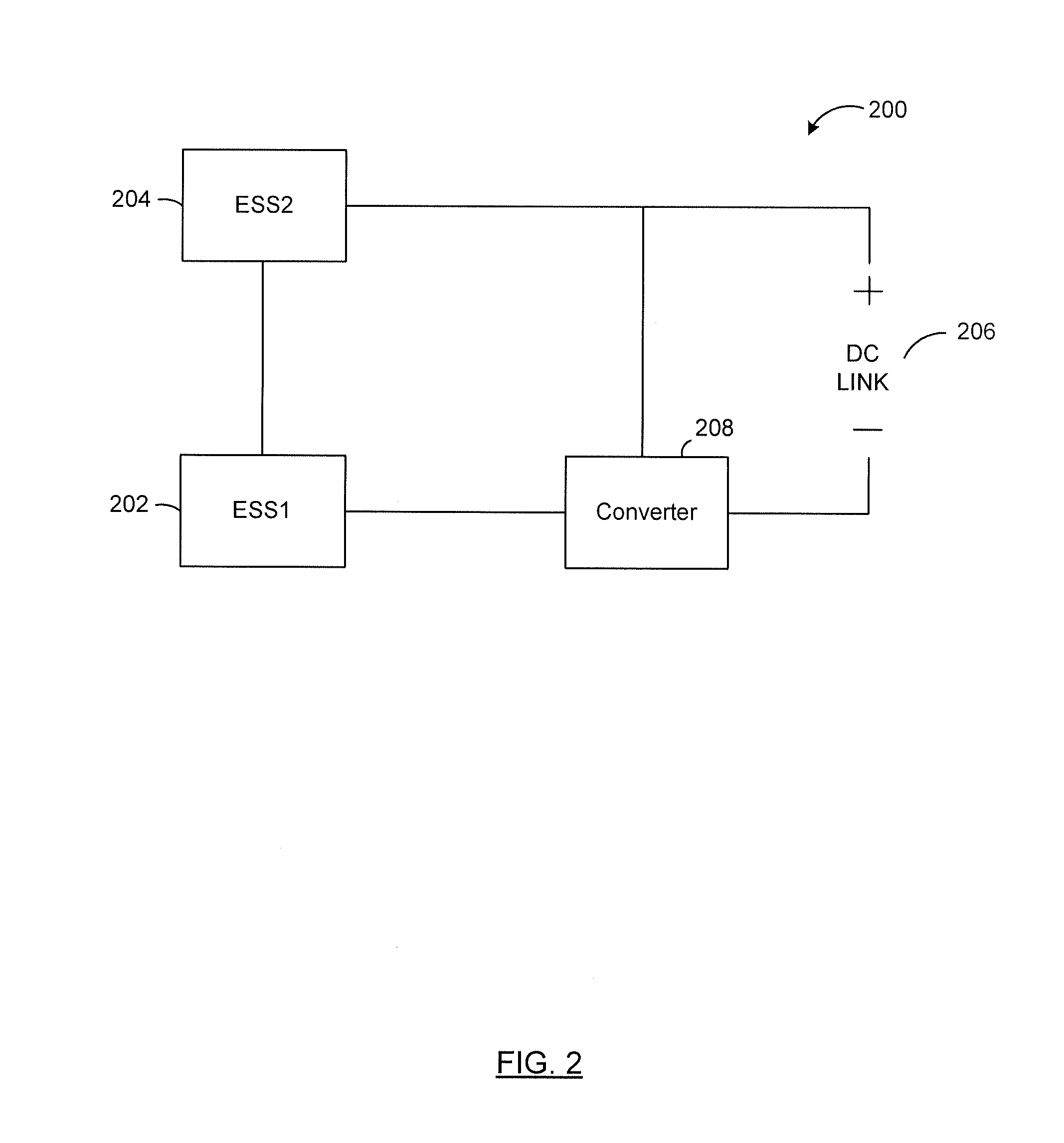
The invention provides a reconfigurable energy storage system that can adjust its power output based on the needs of a load. The system includes two energy storage systems and a power converter that can manipulate the transfer of power between the two systems based on the state of charge of each system, the load, and the capabilities of the energy storage systems. The system can also include a third energy storage system that generates electrical energy or provides higher energy density. The technical effect of the invention is a flexible and adaptable energy storage system that can adjust its power output to meet different load requirements.

Problems solved by technology

Typically, energy storage systems used in EV, HEV and PHEV applications do not optimize at the same time energy, power and life cycle of the various components within the energy storage system.
Furthermore, such energy storage systems tend to be expensive, heavy in weight and / or bulky in size.
This can result in inefficient vehicle performance and unsatisfactory customer experience.

Method used


Image

  • Reconfigurable hybrid energy storage system for electrified vehicles
  • Reconfigurable hybrid energy storage system for electrified vehicles
  • Reconfigurable hybrid energy storage system for electrified vehicles

Examples


Embodiment Construction

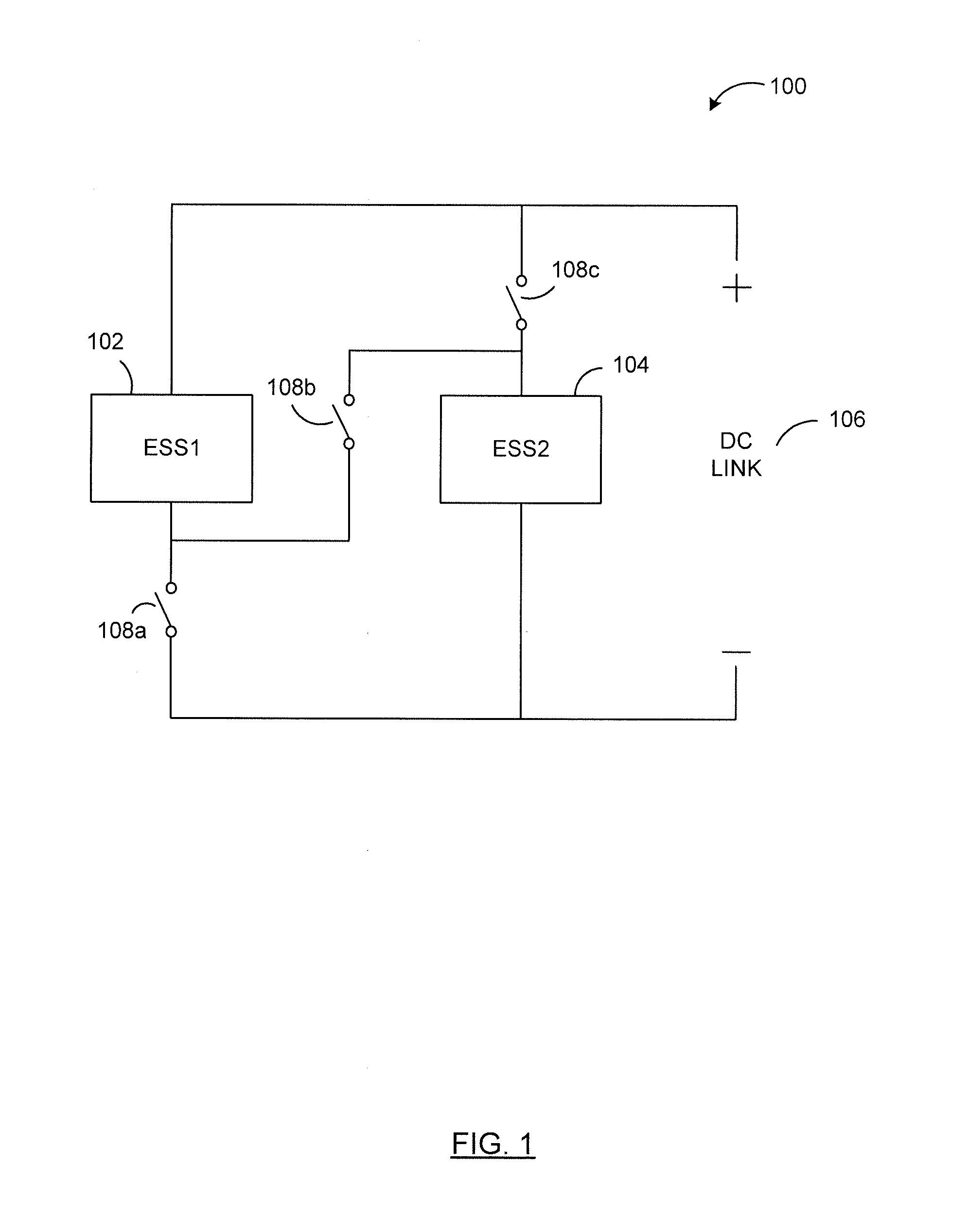
[0080]Reference is first made to FIG. 1, which illustrates a reconfigurable energy storage system 100 according to an example embodiment. Reconfigurable energy storage system 100 includes a first energy storage system 102, a second energy storage system 104, a DC link 106 and a plurality of switches 108a, 108b and 108c.

[0081]Switch 108a is coupled between the first energy storage system 102 and the negative terminal of the DC link 106. Switch 108c is coupled between the positive terminal of the DC link 106 and the second energy storage system 104. Switch 108b is connected between the negative terminal of the first energy storage system 102 and the positive terminal of the second energy storage system 104.

[0082]An energy storage system may be any device or a combination of devices that provides electrical energy. An energy storage system may provide electrical energy by either generating electrical energy and / or storing electrical energy. Examples of an energy storage system, such a...


PUM


Abstract

The embodiments described herein relate to a reconfigurable energy storage system. In one embodiment, the reconfigurable energy storage system comprises a first energy storage system, a second energy storage system and a power converter. The power converter determines a first power level, a second power level and a load coupled to the power converter and manipulates the power transfer between the energy storage systems based on the first power level, the second power level and the load. In another embodiment, the reconfigurable energy storage system also comprises a third energy storage system. In this embodiment, the power converter determines a third power level corresponding to the third energy storage system and manipulates the power transfer between the energy storage systems based also on the third power level. The third power level may correspond to a state of charge of the third energy storage element or amount of power generated by the third energy storage system.

Description

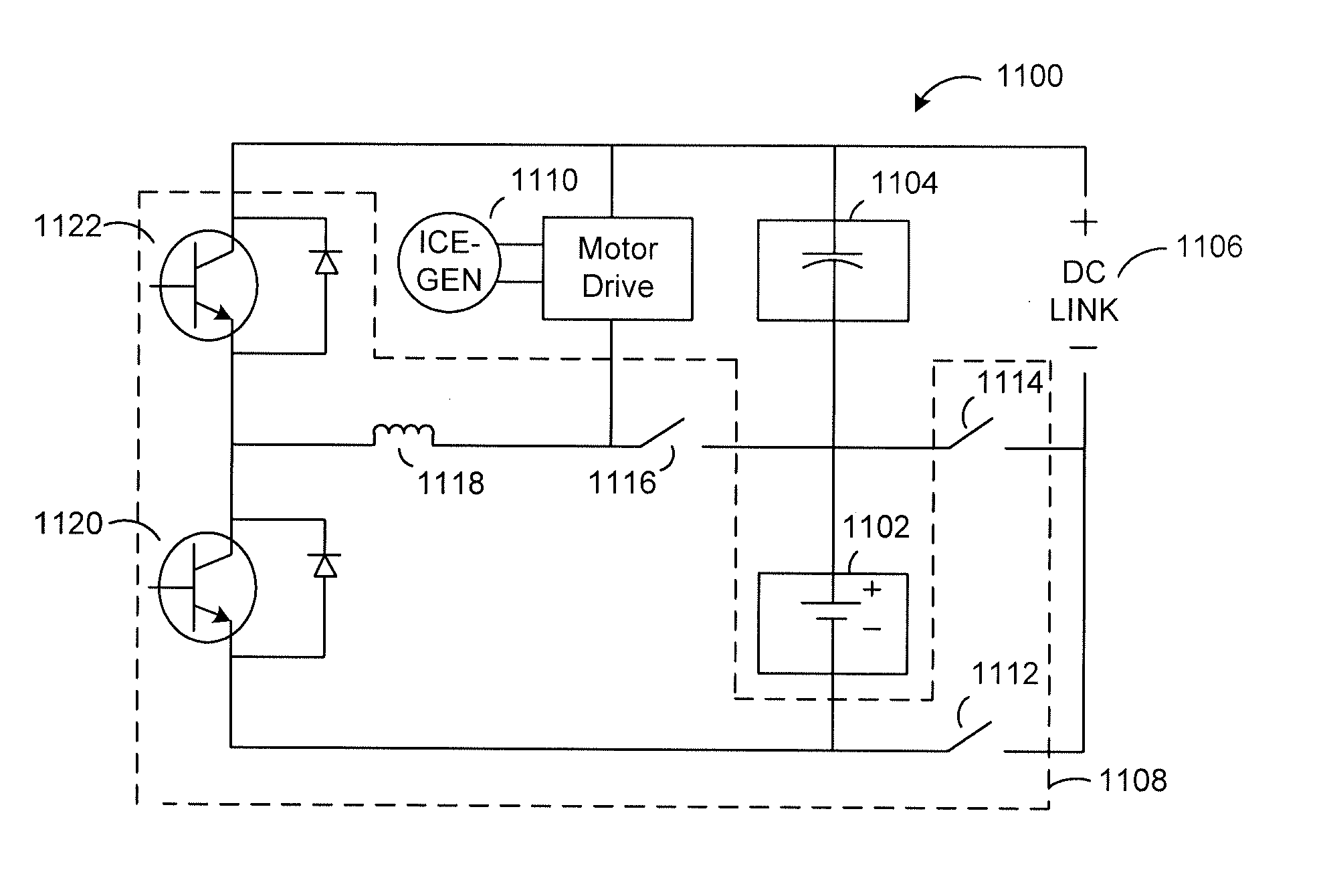
CROSS-REFERENCE TO RELATED APPLICATION[0001]This application claims the benefit of U.S. Provisional Patent Application No. 61 / 835,930 filed Jun. 17, 2013, the contents of which are incorporated herein by reference.FIELD[0002]The described embodiments relate to reconfigurable energy storage systems. More particularly, the embodiments relate to reconfigurable energy storage systems for electric, hybrid and plug-in hybrid vehicle applications.INTRODUCTION[0003]In electric (EV), hybrid electric (HEV) and plug-in hybrid electric (PHEV) vehicle applications, the energy storage system has a direct impact on the vehicle performance during various stages of vehicle operation, such as, for example, during regenerative braking, acceleration, cruising etc.[0004]Typically, energy storage systems used in EV, HEV and PHEV applications do not optimize at the same time energy, power and life cycle of the various components within the energy storage system. Furthermore, such energy storage systems te...

Claims


Application Information

Patent Timeline
Patent Type & Authority Applications(United States)
IPC IPC(8): B60L11/18H02J1/00
CPCB60L11/1861H02J2001/008H02J1/00B60L3/0092B60L7/14B60L15/007B60L2200/12B60L2210/10B60L2210/30B60L2210/40B60L2220/46B60L2240/12B60L2240/14B60L2240/427B60L2240/429B60L2240/547B60L2240/549B60L2260/28B60L2240/527B60L2220/44B60L2240/486H02J7/0024H02J7/345Y02T10/92B60L50/40B60L50/20B60L50/61B60L50/16B60L50/51B60L58/19B60L58/22B60L58/20B60L50/66B60L58/40B60L58/12H02J7/0048H02J1/082H02J7/342B60L58/18Y02T10/62Y02T10/64Y02T10/70Y02T10/72Y02T10/7072B60L3/0046Y02T90/40
Inventor TU, CHIA-HAOEMADI, ALI
Owner ENEDYM INC
Learn More