
Door Actuator

a technology for actuators and doors, applied in door/window fittings, building braking devices, construction, etc., can solve the problems of affecting the installation speed of the door actuator, the minimum tilting of the door piston within the guide, and the negative effect of the minimal tilting of the door piston in prior art applications

Active Publication Date: 2014-12-18
DORMAKABA DEUT GMBH
View PDF15 Cites 0 Cited by
  • Summary
  • Abstract
  • Description
  • Claims
  • Application Information

AI Technical Summary

Benefits of technology

The present invention provides a door operator that is cost-effective and easy to install. It has a high efficiency and requires minimal force to move the piston. The invention solves the problem of minimal tilting of the piston in prior art applications, which improves the efficiency of the door operator. The opening piston has a first pressure roller that allows for a low-friction transmission of forces between the piston and the cam disc, and a second pressure roller that allows for a low-friction transmission of forces between the damping piston and the cam disc. The cylinder element is securely connected to the opening piston and the damping piston, providing double support and stabilization of the opening piston to prevent tilting and improve the efficiency of the door closer.

Problems solved by technology

The prior art door operators with a cam disc very often encountered the problem that the two pistons are minimally tilting within their guide.
As a consequence, a higher expenditure of forces was required to move the piston.
In particular when opening the door and thus when moving the opening piston against the closing spring, this minimal tilting of the piston was negatively noticed in prior art applications.

Method used


Image

  • Door Actuator
  • Door Actuator
  • Door Actuator

Examples


Embodiment Construction

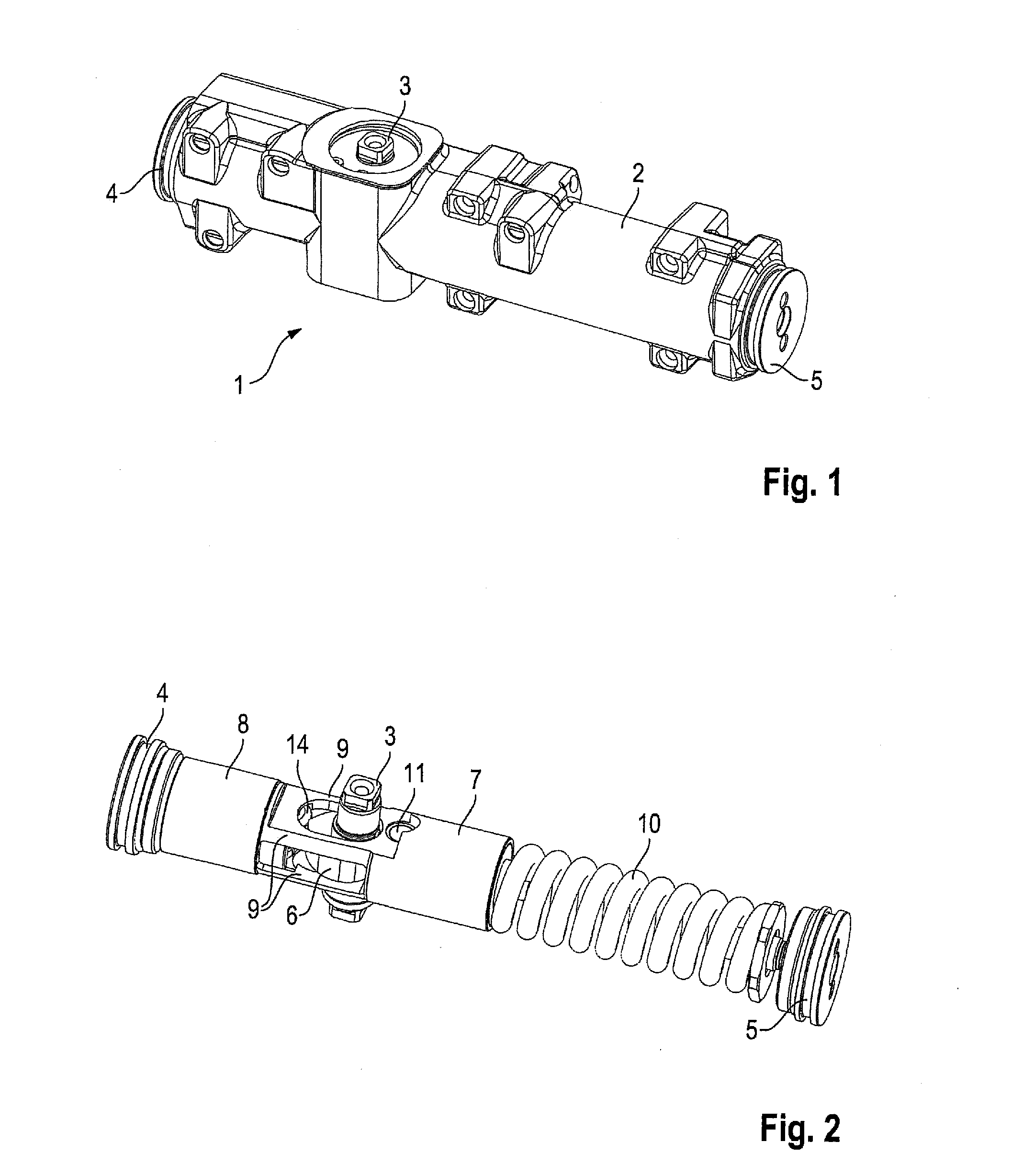
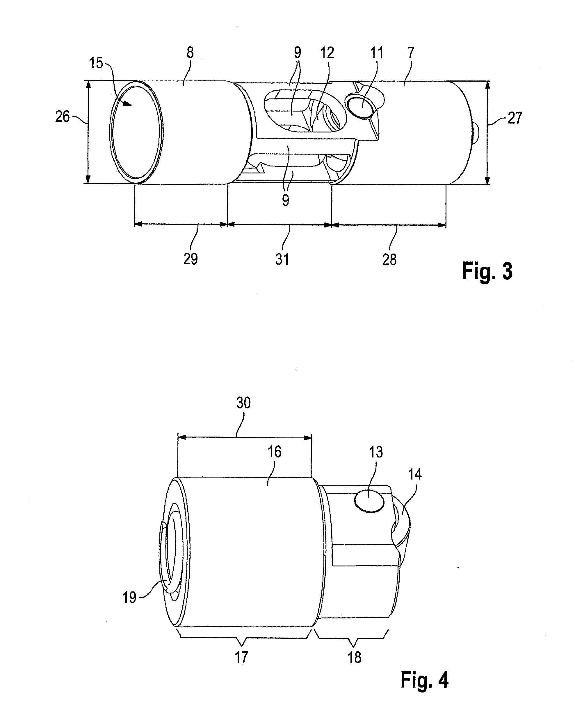
[0029]In the following, the door operator, formed as a door closer 1, will be explained in detail based on the FIGS. 1 to 5.

[0030]FIG. 1 shows the door closer 1. Essentially, the door closer 1 comprises a cylindrically shaped housing 2. The two frontal side ends of the housing 2 are closed off by a first cover 4 and a second cover 5. An output shaft 3 of the door closer 1 protrudes from the housing 2. An arm assembly, for example, is attached to output shaft 3. It is via this arm assembly that the force is transferred onto the door leaf, respectively onto the wall, or onto the door transom.

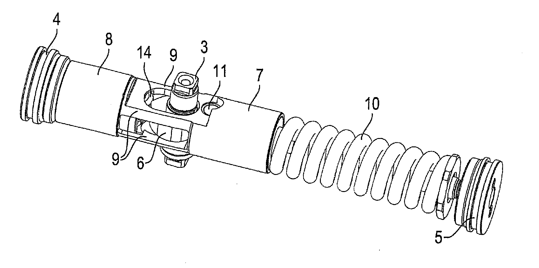
[0031]In FIG. 2, the housing 2 of the door closer 1 is not shown. Furthermore, as can be seen in FIG. 2, the door closer 1 comprises a cam disc 6, which is connected to the output shaft 3 in a torque-proof manner. An opening piston 7 is located on one side of the cam disc 6. The opening piston 7 is supported in the housing 2 to be linearly movable. For this purpose, the envelope surface of the ope...


PUM


Abstract

A door operator for operating a door includes a housing, an output shaft with a cam disc, an opening piston guided in the housing, which piston, on a first side, bears against the cam disc, an energy accumulator acting upon the opening piston for storing a closing energy for the door, and a damping piston guided in a cylindrically shaped hollow space of a cylinder element, and which piston, on a second side, bears against the cam disc, wherein the cylinder element is firmly connected to the opening piston.

Description

CROSS-REFERENCE TO RELATED APPLICATIONS[0001]This is a U.S. national stage of application No. PCT / EP2012 / 004723, filed on 14 Nov. 2012, which claims priority to the German Application No. 10 2011 055 974.4, filed 2 Dec. 2011, the content of both incorporated herein by reference.BACKGROUND OF THE INVENTION[0002]1. Field of the Invention[0003]The present invention relates to a door operator, in particular to a door closer for operating a door.[0004]2. Related Art[0005]Door operators are understood to be in particular door closers, servo-assisted door closers and door drives. In door closers, an energy accumulator is usually pre-loaded by manually actuating the door leaf. The door can be closed again without manual actuation by discharging the energy accumulator. The door closers are either attached directly to the door leaf, to a door transom or to a wall. With an attachment to a door leaf, an arm assembly is attached to the output shaft of the door closer. It is via this arm assembly...

Claims


Application Information

Patent Timeline
Patent Type & Authority Applications(United States)
IPC IPC(8): E05F3/12E05F3/04
CPCE05F3/04E05F3/12E05F3/104E05Y2900/132E05F3/227
Inventor SALUTZKI, THOMASHELLWIG, ALEXANDERMEULENBELD, JAN
Owner DORMAKABA DEUT GMBH
Learn More