Liquid container
- Summary
- Abstract
- Description
- Claims
- Application Information
AI Technical Summary
Benefits of technology
Problems solved by technology
Method used
Image

Examples
embodiment 1
Configuration of Liquid Jet System 1000
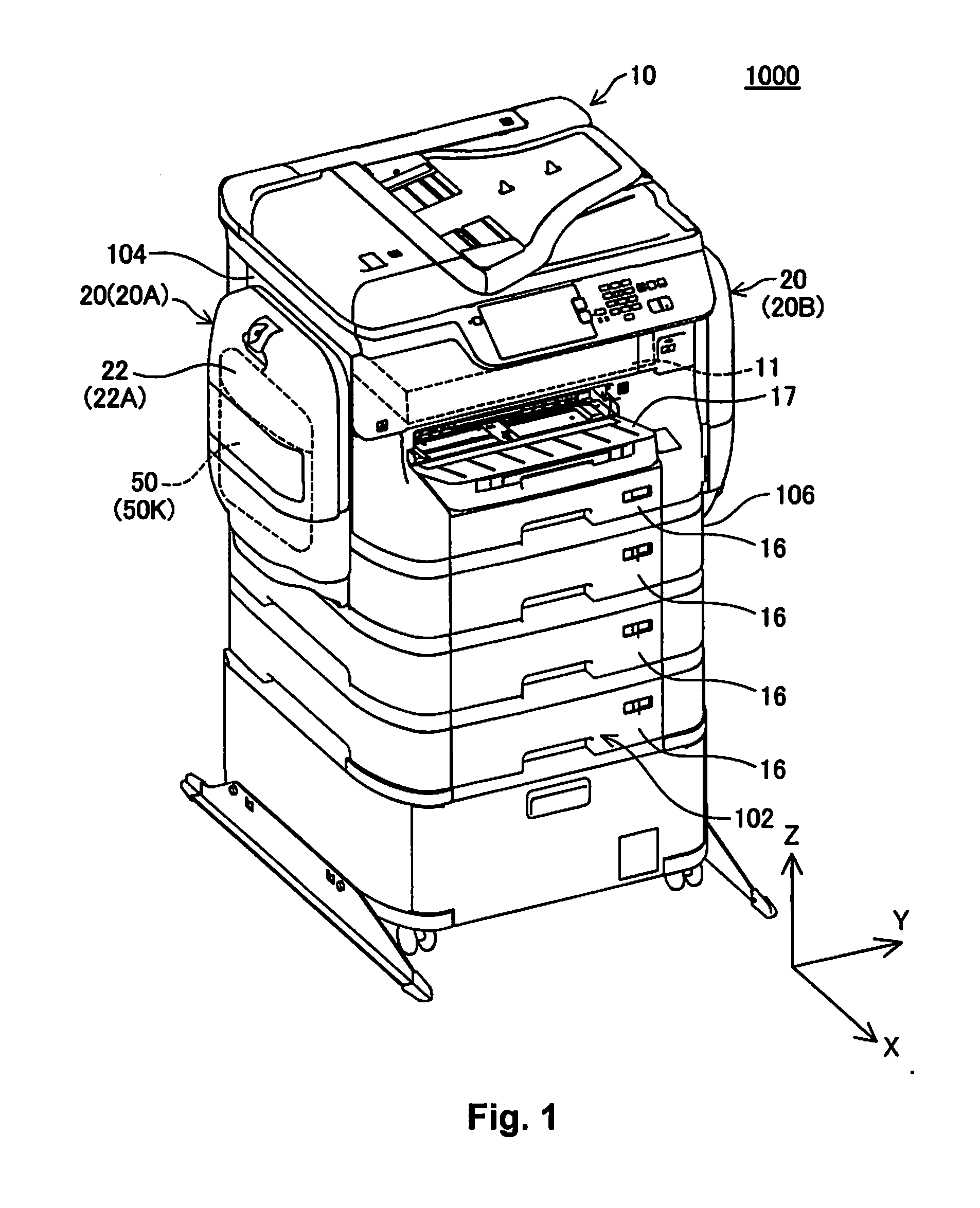
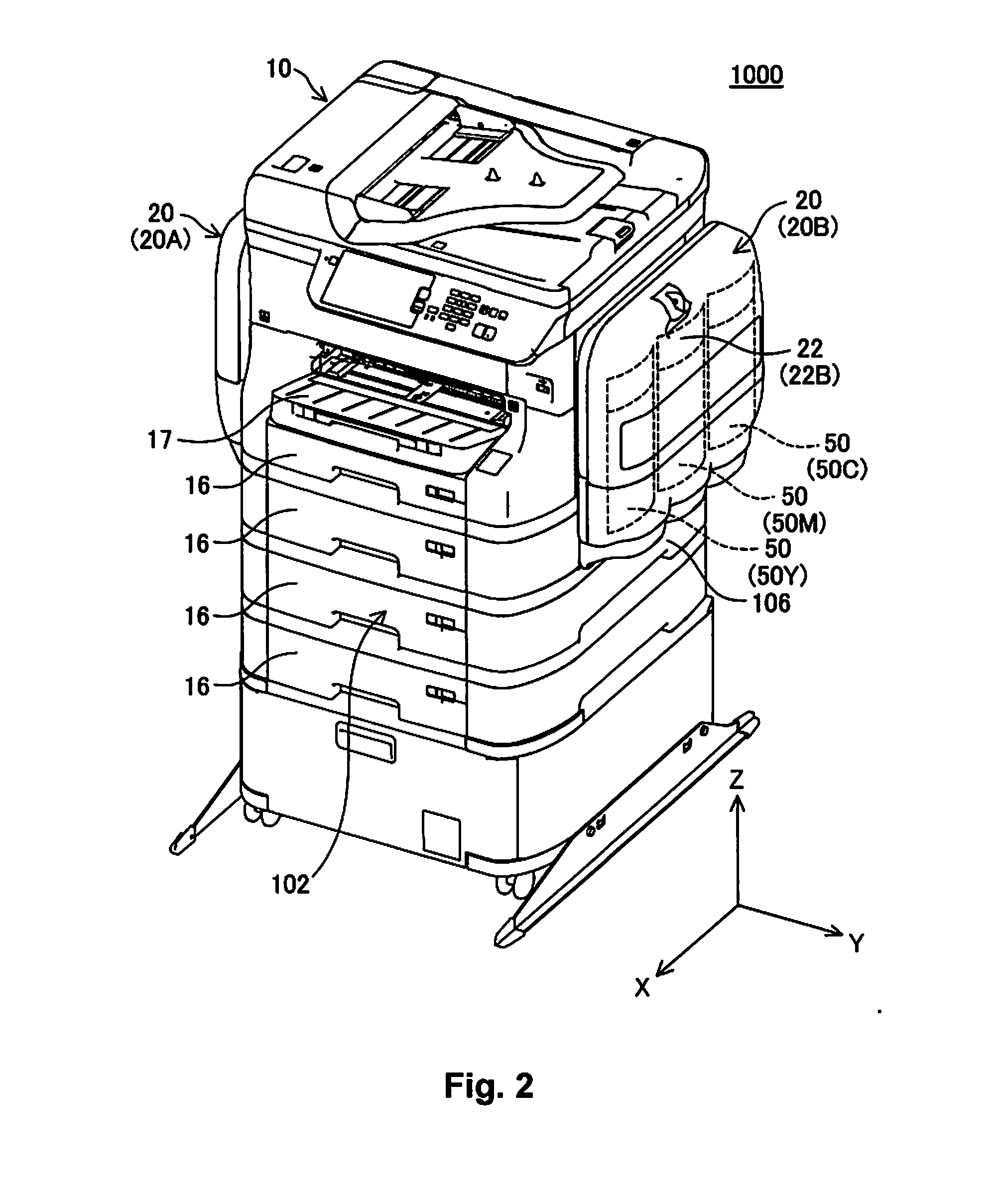
[0077]FIGS. 1 and 2 are perspective views illustrating the outer appearance of a liquid jet system 1000. As illustrated in FIG. 1, the liquid jet system 1000 is provided with a printer 10 and two liquid supply apparatuses 20. The two liquid supply apparatuses 20 are each provided to two ends of the printer 10. In the state of use of the liquid jet system 1000, the printer 10 is installed on a horizontal surface. The XY plane is the horizontal plane, and the Z-axis direction is the direction of the force of gravity. The positive orientation of the Z-axis direction is the upward orientation in the direction of the force of gravity, and the negative orientation of the Z-axis direction is the downward orientation in the direction of the force of gravity. Below, the positive orientation of the Z-axis direction shall be denoted by the “+Z-axis direction” and the negative orientation of the Z-axis direction shall be denoted by the “−Z-axis direction”....
embodiment 2
[0245]The embodiment 2 is different from the embodiment 1 in that a filter unit 700 is provided to the liquid storage bag 52 interior. FIG. 53 is a perspective view illustrating a preparatory stag of the step P810 in the ink sealing process (FIG. 14). FIG. 54 is a perspective view illustrating a stage where the step P810 is complete. The filter unit 700 has a flow path provided to the interior (see FIGS. 55, 58) and is connected between the operation member 53 and the flow path member 72, as illustrated in FIG. 54.
[0246]FIGS. 55 and 56 are perspective views illustrating an exploded view of the filter unit 700. The filter unit 700 is provided with a frame 710, a filter chamber frame 720, a filter 725, and a deaeration chamber film 730. The frame 710 is provided with an upper connection part 711, a lower connection part 712, a flow path chamber 715, a through hole 716, and a deaeration chamber 735.
[0247]The frame 710 is formed by, for example, resin molding. The filter 725 does allow ...
embodiment 3
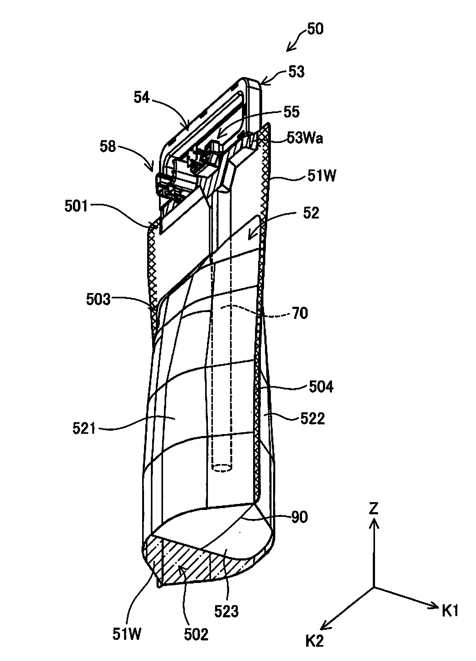
[0252]FIG. 59 is a front view illustrating a liquid container 50a. FIG. 60 is a side view illustrating the liquid container 50a in the mounted state, and illustrates a state where the amount of ink remaining is substantially zero. The liquid container 50a is intended to be mounted onto the detachable unit 30 as an alternative to the liquid container 50.
[0253]The liquid container 50a is provided with a liquid storage bag 52a. The liquid storage bag 52a is formed when two films are bonded together, and, unlike the liquid container 50, does not have a gusset part. The hatching illustrated in FIG. 49 illustrates a welded part 50aY where the two films are welded together. The welded part 50a forms a shape like a pentagon; the reason why liquid is not stored near the corners near the bottom part is in order to reduce the amount of storage.
[0254]The liquid storage bag 52a is bonded to the operation member 53. This operation member 53 is the same as the one included with the liquid containe...
PUM
 Abstract
Description
Claims
Application Information
 - R&D
- Intellectual Property
- Life Sciences
- Materials
- Tech Scout
- Unparalleled Data Quality
- Higher Quality Content
- 60% Fewer Hallucinations
Browse by: Latest US Patents, China's latest patents, Technical Efficacy Thesaurus, Application Domain, Technology Topic, Popular Technical Reports.
© 2025 PatSnap. All rights reserved.Legal|Privacy policy|Modern Slavery Act Transparency Statement|Sitemap|About US| Contact US: help@patsnap.com