
Method and Engineering Apparatus for Performing a Three-Dimensional Analysis of a Technical System

Inactive Publication Date: 2014-12-04
SIEMENS AG
View PDF11 Cites 9 Cited by
  • Summary
  • Abstract
  • Description
  • Claims
  • Application Information

AI Technical Summary

Benefits of technology

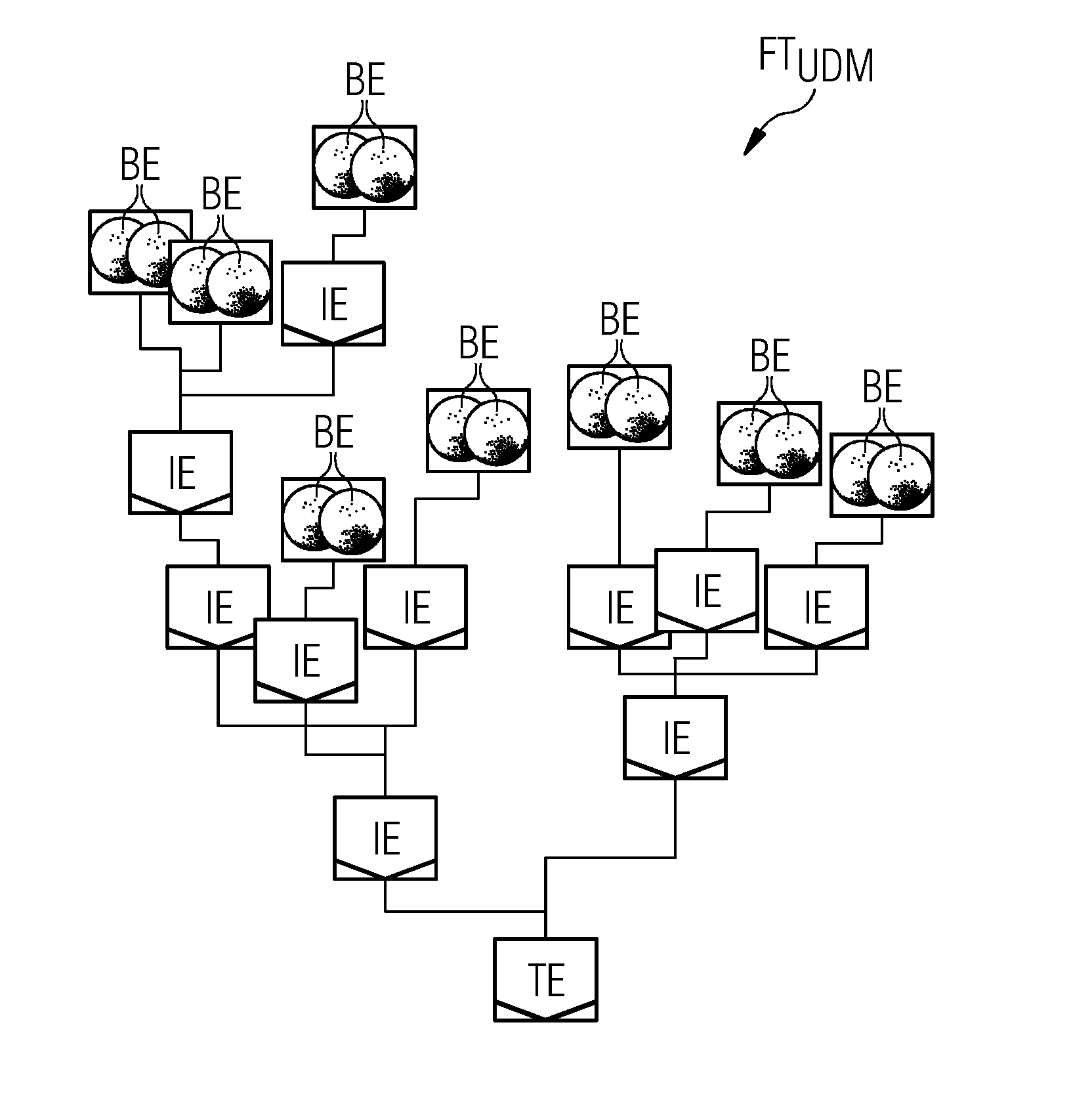
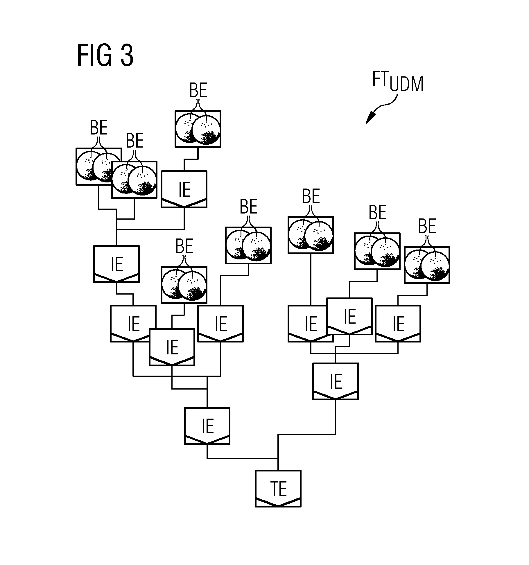
The present invention provides a method and apparatus for performing a three-dimensional analysis of an investigated technical system using a fault tree representation. The method includes outputting analysis data of each event in the fault tree to a user through a three-dimensional body with projection surfaces. The fault tree can have several levels, and each level can represent a logical combination of events. The events of the fault tree can represent faults or technical components of the system. The method can also include displaying the events in a nested or unfolded display mode, and can use simulation or sensor data to provide failure data. The engineering tool includes program code for performing the method. The technical effect of the invention is to provide a high degree of transparency and understanding of the investigated technical system.

Problems solved by technology

With increasing complexity of technical systems, computer-implemented tools and analyzing methods are used.
Typical top events may be, for example, a total loss of production of a production facility, the unavailability of a safety system, a toxic emission, an aircraft crash or even a nuclear reactor core melt.
For example, if any minimal cut set contains a single basic event, then the top level event may be caused by a single failure.
In a complex technical system, where on each level of the fault tree, a plurality of heterogeneous evaluation results or data is available, the conventional fault trees may no longer provide efficient transparency of the interrelations between the events and corresponding components.
Accordingly, conventional fault trees displayed to a user by the analyzing tool are not easy to understand for a user.
Since a user becomes easily lost in the conventional fault tree, it becomes very difficult for the user to recognize relevant interrelations that may be used for planning a complex technical system.
For example, an interactive and intuitive information request as well as editing or modeling a technical system in a two-dimensional fault tree is cumbersome and confusing.

Method used


Image

  • Method and Engineering Apparatus for Performing a Three-Dimensional Analysis of a Technical System
  • Method and Engineering Apparatus for Performing a Three-Dimensional Analysis of a Technical System
  • Method and Engineering Apparatus for Performing a Three-Dimensional Analysis of a Technical System

Examples


Embodiment Construction

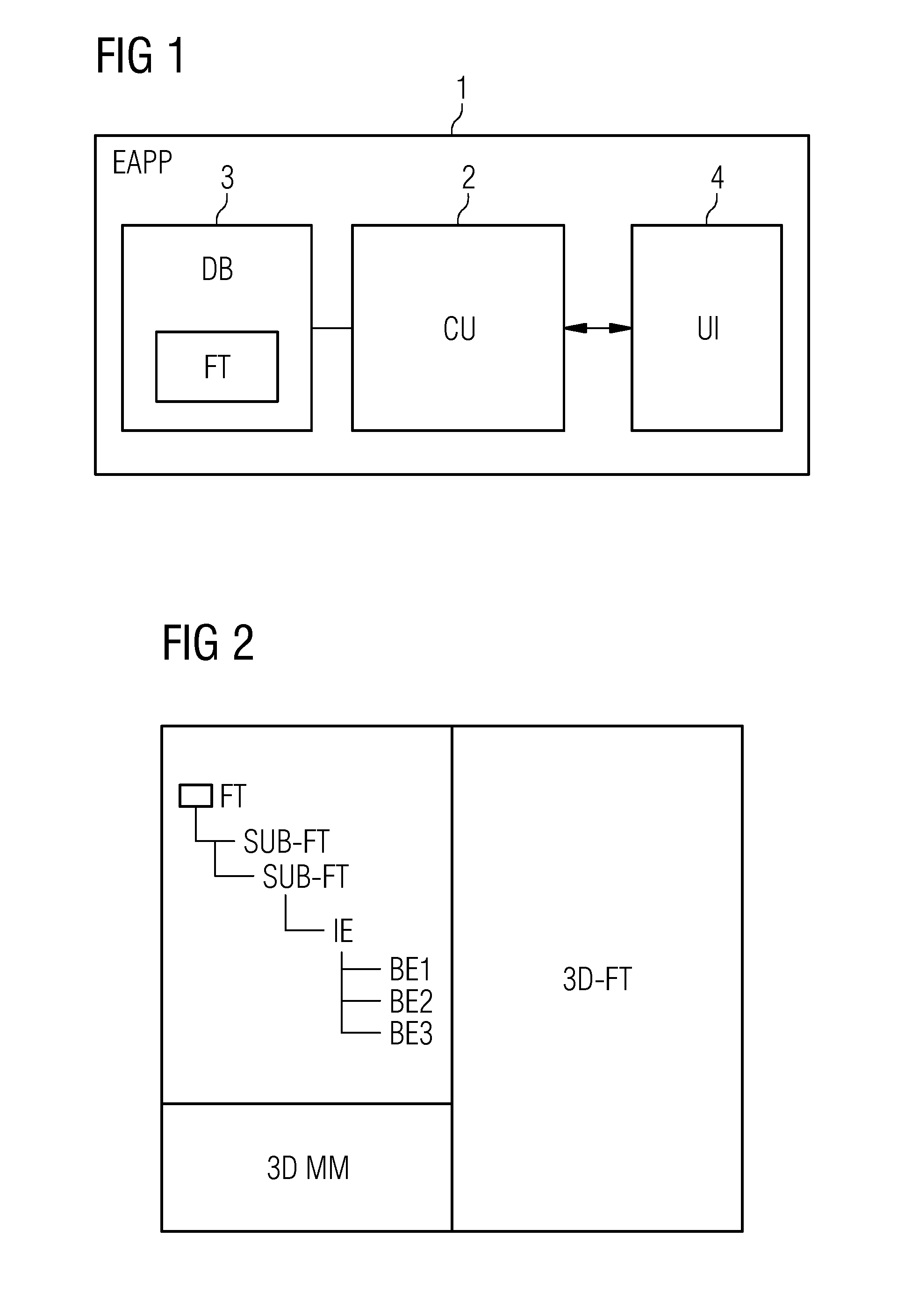
[0028]As shown in FIG. 1, an engineering apparatus 1 according to one or more embodiments and a calculation unit 2 including one or more microprocessors are connected to a database 3. The database 3 stores a constructed three-dimensional fault tree FT of an investigated technical system. The investigated technical system may be a complex technical system including a plurality of components (e.g., a vehicle such as a car or an aircraft, a power plant or a production facility). The three-dimensional fault tree FT stored in the database 3 includes basic events BE linked logically to a top event of the investigated technical system. The events of the fault tree FT may represent technical components or subsystems of the investigated technical system. The fault tree FT of the investigated system may include levels L including levels of basic events that are linked logically via levels of intermediate events to a top level event TE. The top level includes the top event TE representing an u...


PUM


Abstract

A method for performing a three-dimensional analysis of an investigated technical system represented by a corresponding fault tree is provided. The method includes linking basic events logically to a top event of the investigated system. The fault tree is a three-dimensional fault tree. Each event of the fault tree is represented by a three-dimensional body having projection surfaces adapted to output analysis data of the respective event to a user.

Description

[0001]This application claims the benefit of EP 13169503, filed on May 28, 2013, which is hereby incorporated by reference.BACKGROUND[0002]The present embodiments relate to a method and apparatus for performing a three-dimensional analysis of a complex investigated technical system including technical components. With increasing complexity of technical systems, computer-implemented tools and analyzing methods are used. Already in the first stages of product developments, questions concerning security, reliability, availability, and performance that are relevant for the architecture and implementation of the respective technical system arise.[0003]Reliability and safety engineering is an engineering discipline to assure that the engineered system provides acceptable levels of safety and reliability. Safety engineering provides that a critical system behaves as required even when components of the technical system fail. The goal of safety engineering is to manage risk and to eliminate...

Claims


Application Information

Patent Timeline
IPC IPC(8): G06F11/26
CPCG06F11/26G06N5/00
Inventor SCHWINN, JEAN-PASCALUZELAC, SANJA
Owner SIEMENS AG
Learn More