Charge and discharge control method, charge and discharge control system, and charge and discharge control apparatus
a power storage apparatus and control method technology, applied in electric vehicles, transportation and packaging, ac network load balancing, etc., can solve the problems of power storage apparatus, power storage apparatus, power storage apparatus not being able to continue charge or discharge, etc., to achieve secure output responsiveness
- Summary
- Abstract
- Description
- Claims
- Application Information
AI Technical Summary
Benefits of technology
Problems solved by technology
Method used
Image


Examples
embodiment 1
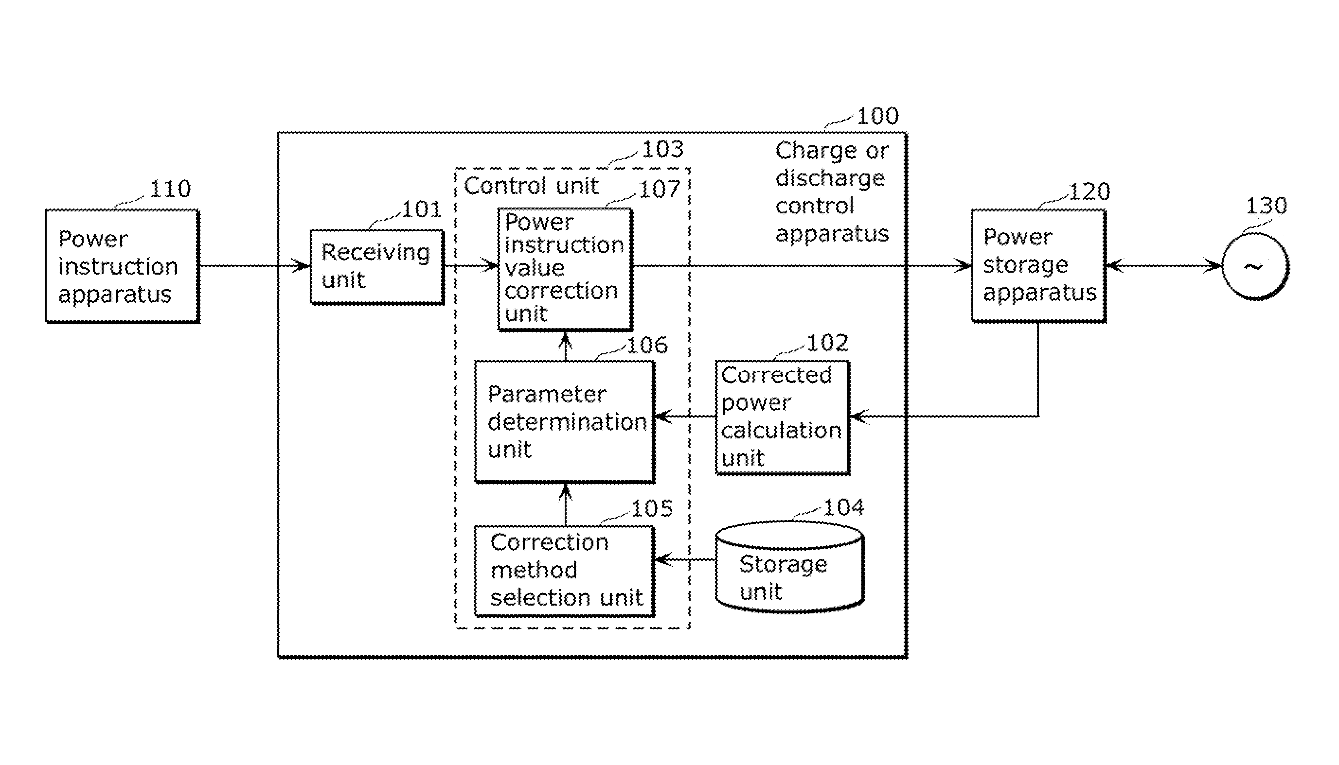
[0068]FIG. 3 is a diagram illustrating an outline of a charge or discharge control apparatus according to Embodiment 1.
[0069]In FIG. 3, a charge or discharge control apparatus 100 is an apparatus which, in a predetermined stabilization control period, controls charge or discharge of a grid 130 of a power storage apparatus 120, by receiving a power instruction value outputted from a power instruction apparatus 110 and by outputting a power instruction value after correction to the power storage apparatus 120. It should be noted that in the present embodiment, the stabilization control period is described as a configuration of a plurality of steps by setting a 10-minute period as a step.
[0070]Moreover, by obtaining the SOC from the power storage apparatus 120, the charge or discharge control apparatus 100 performs charge or discharge of the power storage apparatus 120 which follows the power instruction value in organic collaboration with the power storage apparatus 120, and controls ...
modification 1
(Modification 1)
[0178]Next, Modification 1 of the charge or discharge control apparatus 100 will be described.
[0179]The parameter determination unit 106 of the charge or discharge control apparatus 100 according to Modification 1 obtains the actual corrected power amount in the past predetermined period from the power instruction correction unit 107. Furthermore, the parameter determination unit 106 determines a deviation en, using the difference between the calculated corrected power amount xn in the past predetermined period and the actual corrected power amount in the past predetermined period. The parameter determination unit 106 increases the degree of precision of the future corrected power amount by controlling the corrected parameter pn to get the deviation en close to 0.
[0180]Specifically, the parameter determination unit 106 calculates the corrected parameter pn not by using the expression of the open loop control such as Expression (13) but by using Expression (16) of PI ...
modification 2
(Modification 2)
[0183]Next, Modification 2 of the charge or discharge control apparatus 100 will be described.
[0184]The parameter determination unit 106 of the charge or discharge control apparatus 100 according to Modification 2 dynamically determines, in the above described correction method M1, the delay time (corrected parameter pn) every time receiving the power instruction value using the change amount of the power instruction value.
[0185]When the power instruction value rapidly changes even if the same delay time is set, that is, when the change amount of the power instruction value is large, the degree of delay D and the degree of precision P of the performance score tend to degrade. Meanwhile, when the power instruction value slowly changes, that is, when the change amount of the power instruction value is small, the degree of delay D and the degree of precision P of the performance score tend to be difficult to degrade.
[0186]Therefore, the parameter determination unit 106 ...
PUM
 Abstract
Description
Claims
Application Information
 - R&D
- Intellectual Property
- Life Sciences
- Materials
- Tech Scout
- Unparalleled Data Quality
- Higher Quality Content
- 60% Fewer Hallucinations
Browse by: Latest US Patents, China's latest patents, Technical Efficacy Thesaurus, Application Domain, Technology Topic, Popular Technical Reports.
© 2025 PatSnap. All rights reserved.Legal|Privacy policy|Modern Slavery Act Transparency Statement|Sitemap|About US| Contact US: help@patsnap.com