
Method and module for controlling a vehicle's speed based on rules and/or costs

Active Publication Date: 2014-11-27
SCANIA CV AB
View PDF1 Cites 12 Cited by
  • Summary
  • Abstract
  • Description
  • Claims
  • Application Information

AI Technical Summary

Benefits of technology

The present invention relates to a system for controlling the speed of a vehicle to minimize fuel usage. The system uses a processor to predict the amount of fuel needed and controls the vehicle's speed accordingly. The processor load is independent of the vehicle's power output, weight, and road topology. By controlling the vehicle's speed in this way, the processor can be dimensioned for a uniform load, reducing production costs. Additionally, the system provides a simplified cruise control that is more predictable than previous economical and reference speed-regulating cruise controls.

Problems solved by technology

As a considerable amount of calculations is involved, the processor which is to perform them needs a large capacity.
However, the topography of the itinerary and the vehicle's weight and engine performance may lead to various heavy demands in terms of processor load for determining the reference speed vref.
The reason is that the truck in the first case is likely to accelerate on each downgrade and decelerate on each upgrade, whereas in the second case the truck will find the road substantially level.
The built-in system's processor will thus be subject to relatively large demands if the previously known solutions are applied, since the processor load may vary greatly in different circumstances.

Method used


Image

  • Method and module for controlling a vehicle's speed based on rules and/or costs
  • Method and module for controlling a vehicle's speed based on rules and/or costs
  • Method and module for controlling a vehicle's speed based on rules and/or costs

Examples


Embodiment Construction

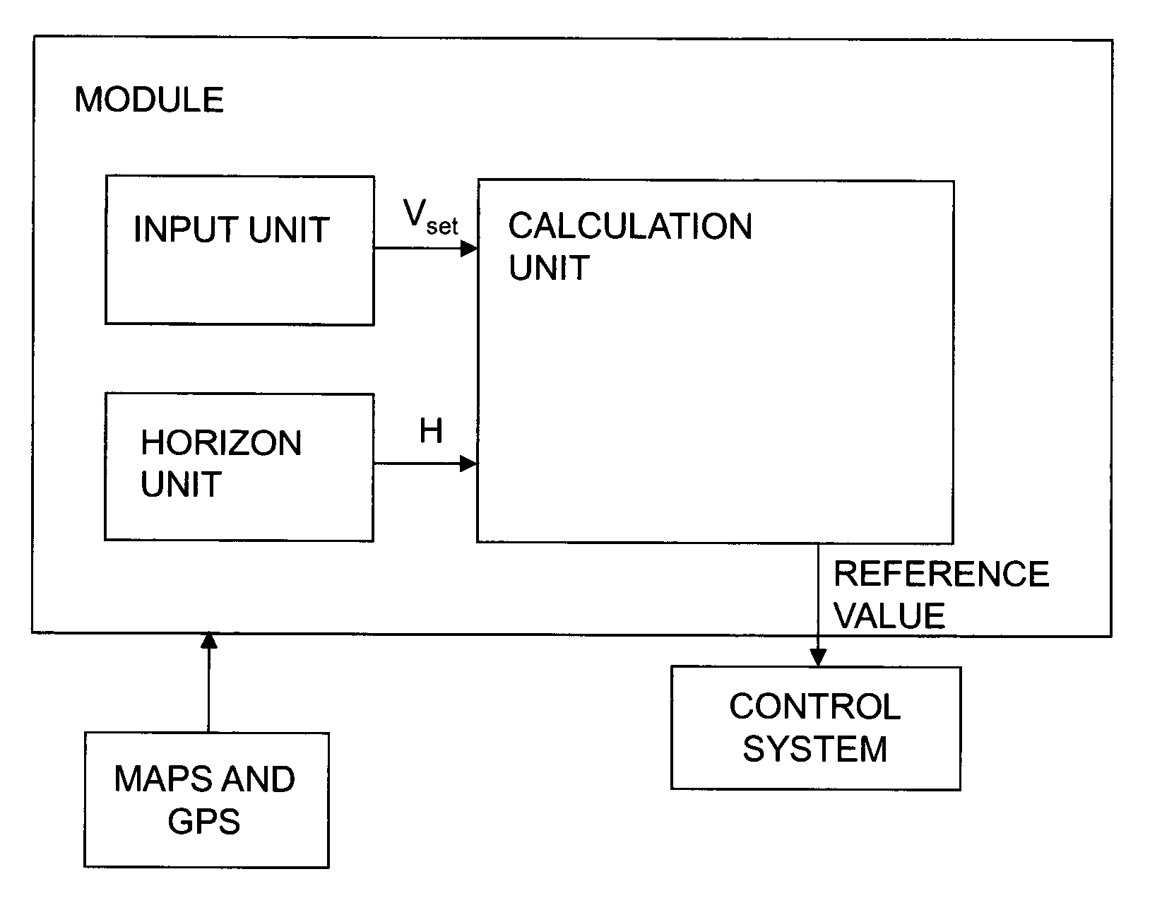
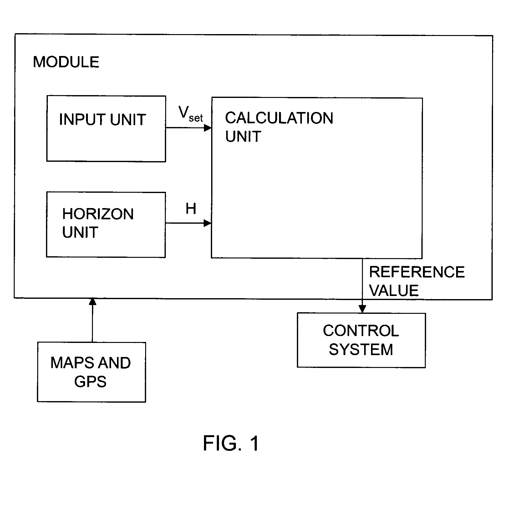
[0039]FIG. 1 depicts a module for controlling a vehicle's speed according to an aspect of the invention. The module comprises an input unit adapted to receiving a desired speed, i.e. a set speed vset, for the vehicle. The driver may for example set a speed vset which he / she wishes the vehicle to maintain. The module comprises also a horizon unit adapted to determining a horizon H for the itinerary by means of map data and location data. The horizon H is made up of route segments with at least one characteristic for each segment. A possible example of characteristics of segments is their gradient α, in radians.

[0040]The description of the present invention states that GPS (global positioning system) is used to determine location data for the vehicle, but specialists will appreciate that other kinds of global or regional positioning systems are conceivable to provide these data. Such positioning systems might for example use radio receivers to determine the vehicle's location. The veh...


PUM


Abstract

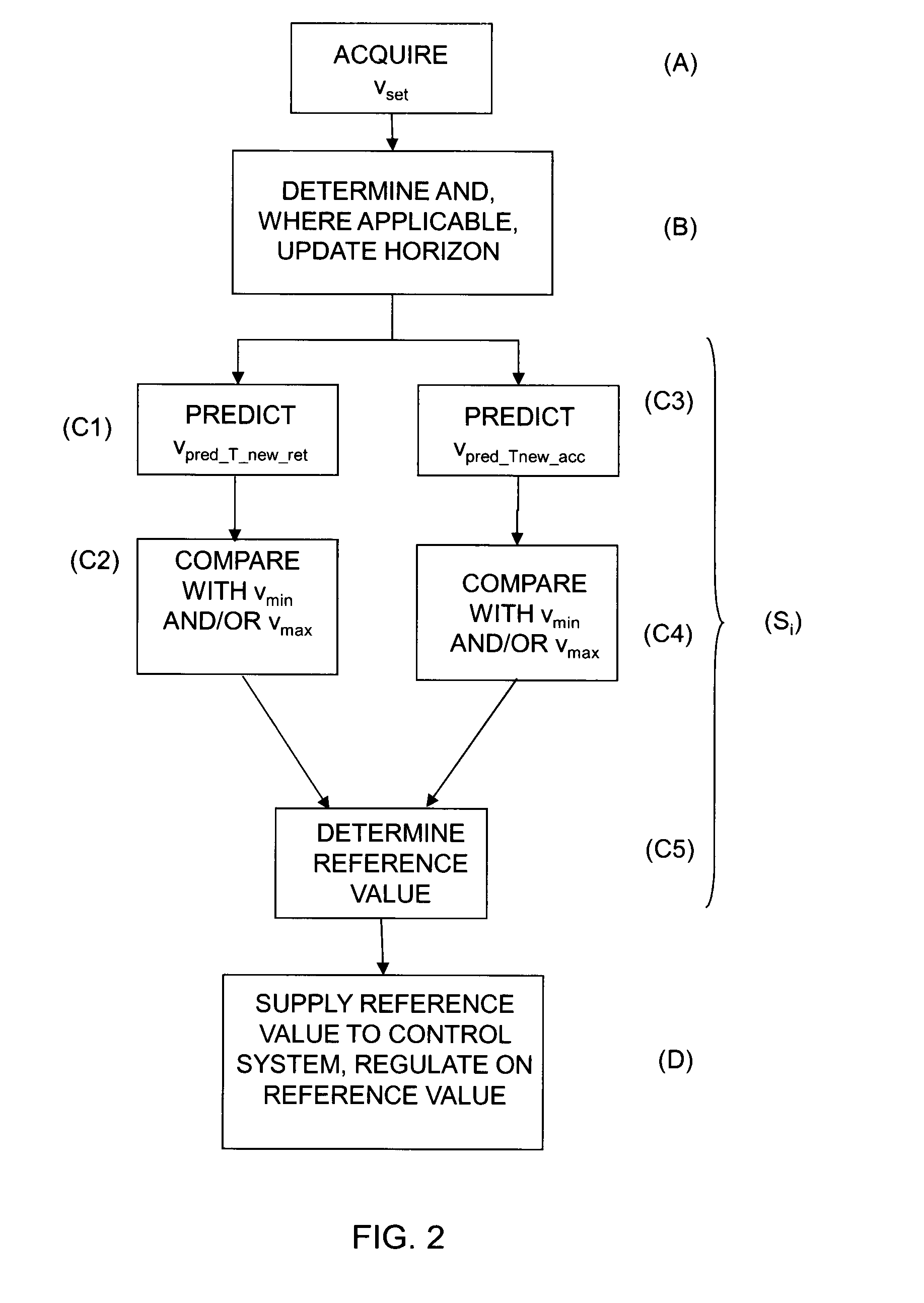
A method for determination of at least one reference value for controlling a vehicle's speed is described. The method may entail making a first prediction vpred<sub2>—< / sub2>Tnew<sub2>—< / sub2>ret and a second prediction vpred<sub2>—< / sub2>Tnew<sub2>—< / sub2>acc of a vehicle speed along a horizon, said first prediction based on an engine torque Tret which retards the vehicle as compared with a conventional cruise control, and said second prediction based on an engine torque Tacc which accelerates the vehicle as compared with a conventional cruise control; comparing said respective first prediction vpred<sub2>—< / sub2>Tnew<sub2>—< / sub2>ret and second prediction vpred<sub2>—< / sub2>Tnew<sub2>—< / sub2>acc of the vehicle speed with a lower limit value vmin and / or an upper limit value vmax which delineate a range within which the vehicle's speed should be; and determining at least one reference value based on at least one of said respective comparisons and said first prediction vpred<sub2>—< / sub2>Tnew<sub2>—< / sub2>ret and second prediction vpred<sub2>—< / sub2>Tnew<sub2>—< / sub2>acc of the vehicle speed along the horizon.

Description

FIELD OF THE INVENTION[0001]The present invention relates to a method and a module for determining at least one reference value which indicates how a vehicle's speed is to be influenced and which can be used to control at least one control system of the vehicle, according to the preambles of the independent claims.BACKGROUND TO THE INVENTION[0002]Cruise control is now usual in motor vehicles, e.g. cars, trucks and buses. An object of cruise control is to achieve a uniform predetermined speed. This is done either by adjusting the engine torque to avoid retardation, or by applying braking action on downhill runs where the vehicle is accelerated by its own weight. A more general object of cruise control is to provide convenient driving and better comfort for the vehicle's driver. A driver of a vehicle equipped with cruise control usually chooses a set speed vset as the speed he / she wishes the vehicle to maintain on level roads. A cruise control then supplies an engine system of the veh...

Claims


Application Information

Patent Timeline
IPC IPC(8): B60W30/14B60W50/08
CPCB60W30/143B60K31/00B60W30/14B60W50/08G05B13/04Y02T10/84B60K2310/244B60W50/0097B60W2710/0666B60W2720/10Y02T10/40B60K31/0066B60W50/00B60W2050/0001
Inventor JOHANSSON, OSKARSÖDERGREN, MARIAROOS, FREDRIK
Owner SCANIA CV AB
Learn More