Systems and methods for measuring electrical power usage in a structure and systems and methods of calibrating the same
a technology of electrical power consumption and electrical circuit breaker panel, which is applied in the field of systems and methods for monitoring electrical power, and can solve problems such as the difficulty of accurately measuring the magnetic field of one or more main electrical power conductors on the surface of electrical circuit breaker panels
- Summary
- Abstract
- Description
- Claims
- Application Information
AI Technical Summary
Benefits of technology
Problems solved by technology
Method used
Image

Examples
first embodiment
[0082]FIG. 6 illustrates an example of electrical current sensor 211, according to the In these examples, electrical current sensor can include: (a) one or more sensors 641 and 642; (b) one or more amplifiers 647 and 648; (c) one or more filters 649 and 650; (d) one or more phase detectors 651; (e) at least one differential amplifier 652; and (f) at least one digitizer 653.
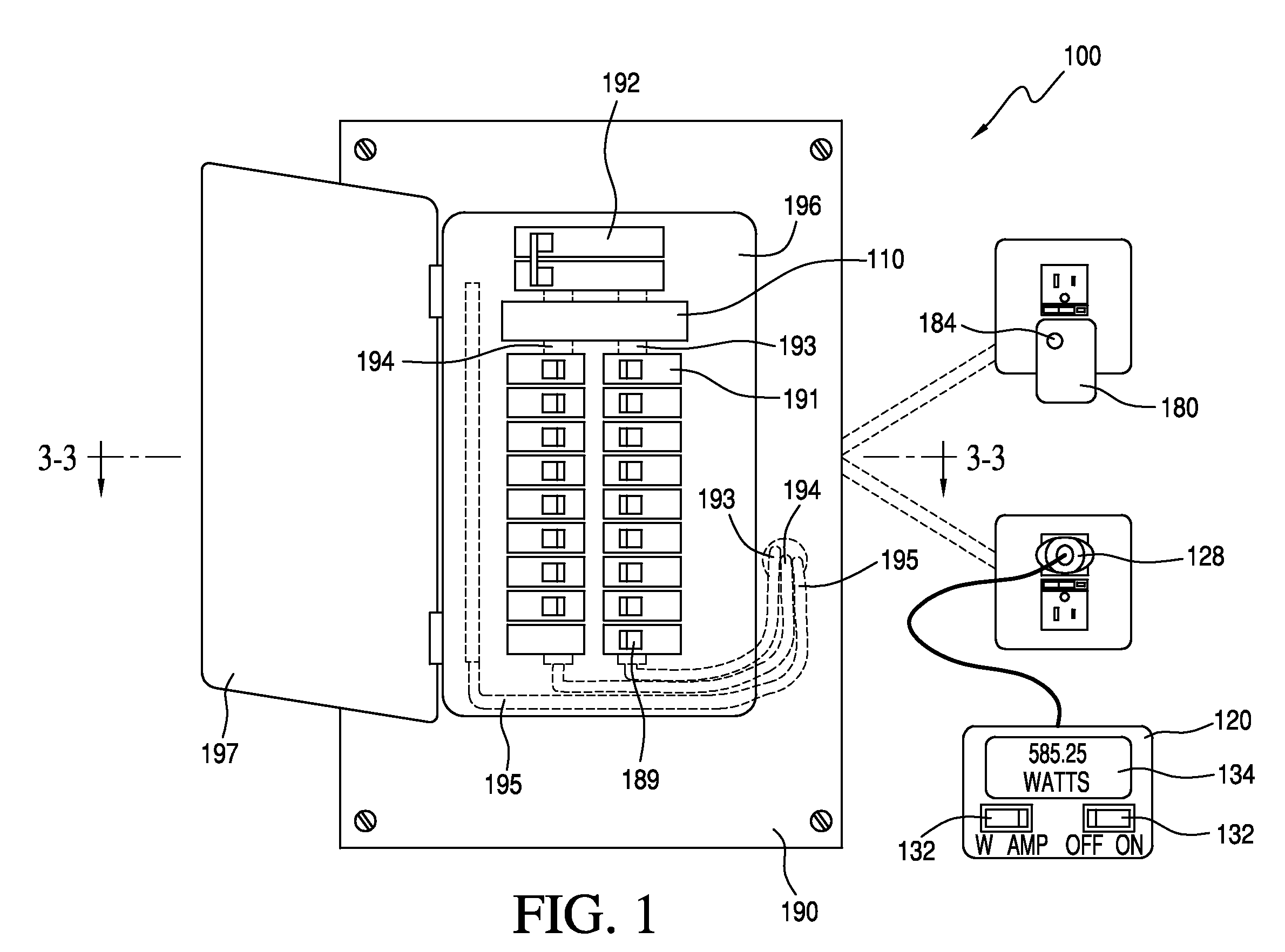
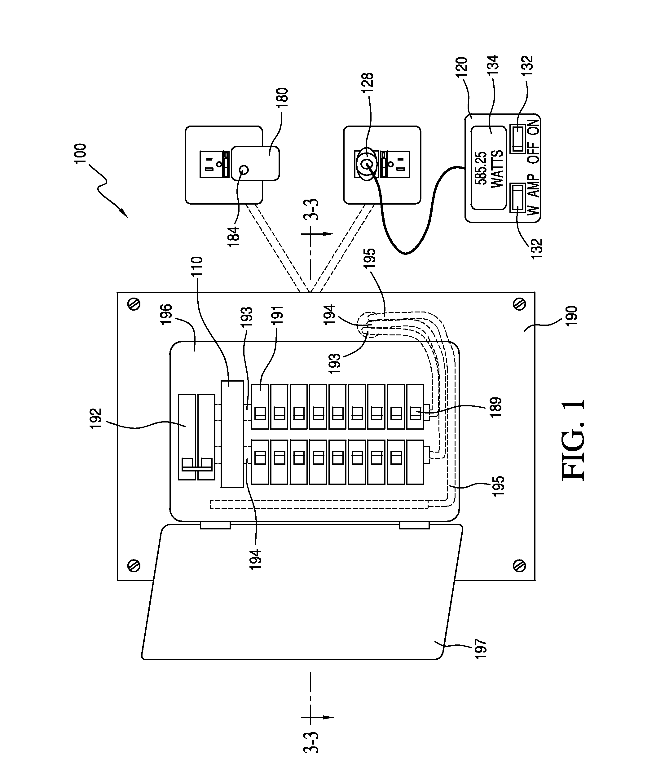
[0083]In some examples, system 100 can be configured to assist the user in the proper placement of sensing device 110 by indicating the proper placement with user communications module 214. In some examples, system 100 can determine proper placement by detecting an approximately 180 degree phase difference between sensors 641 and 642 that are disposed on opposite sides of a conductor (i.e., electrical power conductor 193 or 194). In the same or different examples, user communications module 214 can be co-located with sensing device 110 or user communications module 214 can be used and can be remote and linked to ...
third embodiment
[0120]Specifically, FIG. 14 illustrates an example of switched load 1405, according to a Switched load 1405 can include: (a) switches 1187 and 1442; and (b) calibration loads 1188 and 1441. In this embodiment, switched load 1405 replaces switched load 1105 in calibration device 180 of FIGS. 2 and 11.
[0121]In this embodiment, switched load 1405 can be configured to calibrate the measurement of a single current carrying conductor (a feeder to the branch circuit labeled “Line”) being measured by sensing device 110. In this embodiment, controller 285 can switch between calibration loads 1188 and 1441 to provide two different sets of measurement to use in the calibration process. In other examples, switched load 1405 can include three or more switch of three or more calibration loads.
fourth embodiment
[0122]FIG. 15 illustrates an example of switched load 1505, according to a Switched load 1505 can include: (a) switches 1587 and 1542; and (b) calibration loads 1588 and 1541. In this embodiment, switched load 1505 replaces switched load 1105 in calibration device 180 of FIGS. 2 and 11.
[0123]In this embodiment, switched load 1505 can be designed to calibrate the measurement of two current carrying conductor (a feeder to the branch circuit labeled “Line 1” and “Line 2”) being measured by sensing device 110. In this embodiment, two distinct calibration loads 1588 and 1541 can be switched between individual line conductors and the neutral conductor under the control of a switching signal from controller 285. Controller 285 can control switching signals to electrically couple calibration loads as follows:
Switch Calibration LoadsEnabledCoupledEffectSwitch 1587Calibration load 1541Permit the calibration of ais enabledmeasurement of a feeder to abranch circuit labeled Line 1Switch 1542Cal...
PUM
 Abstract
Description
Claims
Application Information
 - R&D
- Intellectual Property
- Life Sciences
- Materials
- Tech Scout
- Unparalleled Data Quality
- Higher Quality Content
- 60% Fewer Hallucinations
Browse by: Latest US Patents, China's latest patents, Technical Efficacy Thesaurus, Application Domain, Technology Topic, Popular Technical Reports.
© 2025 PatSnap. All rights reserved.Legal|Privacy policy|Modern Slavery Act Transparency Statement|Sitemap|About US| Contact US: help@patsnap.com