Optical detecting device and related method of synchronization adjustment
- Summary
- Abstract
- Description
- Claims
- Application Information
AI Technical Summary
Benefits of technology
Problems solved by technology
Method used
Image
Examples
Embodiment Construction
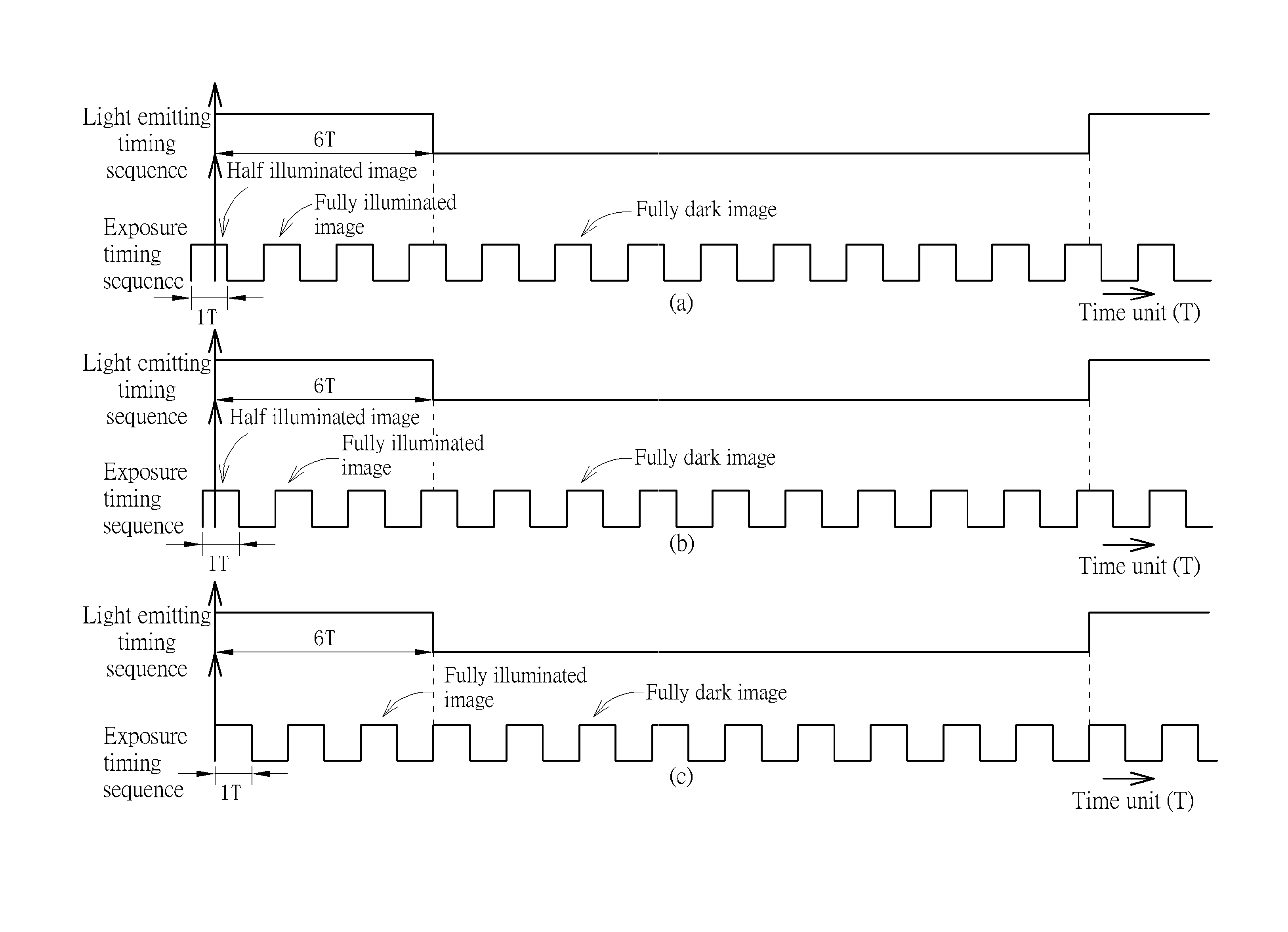
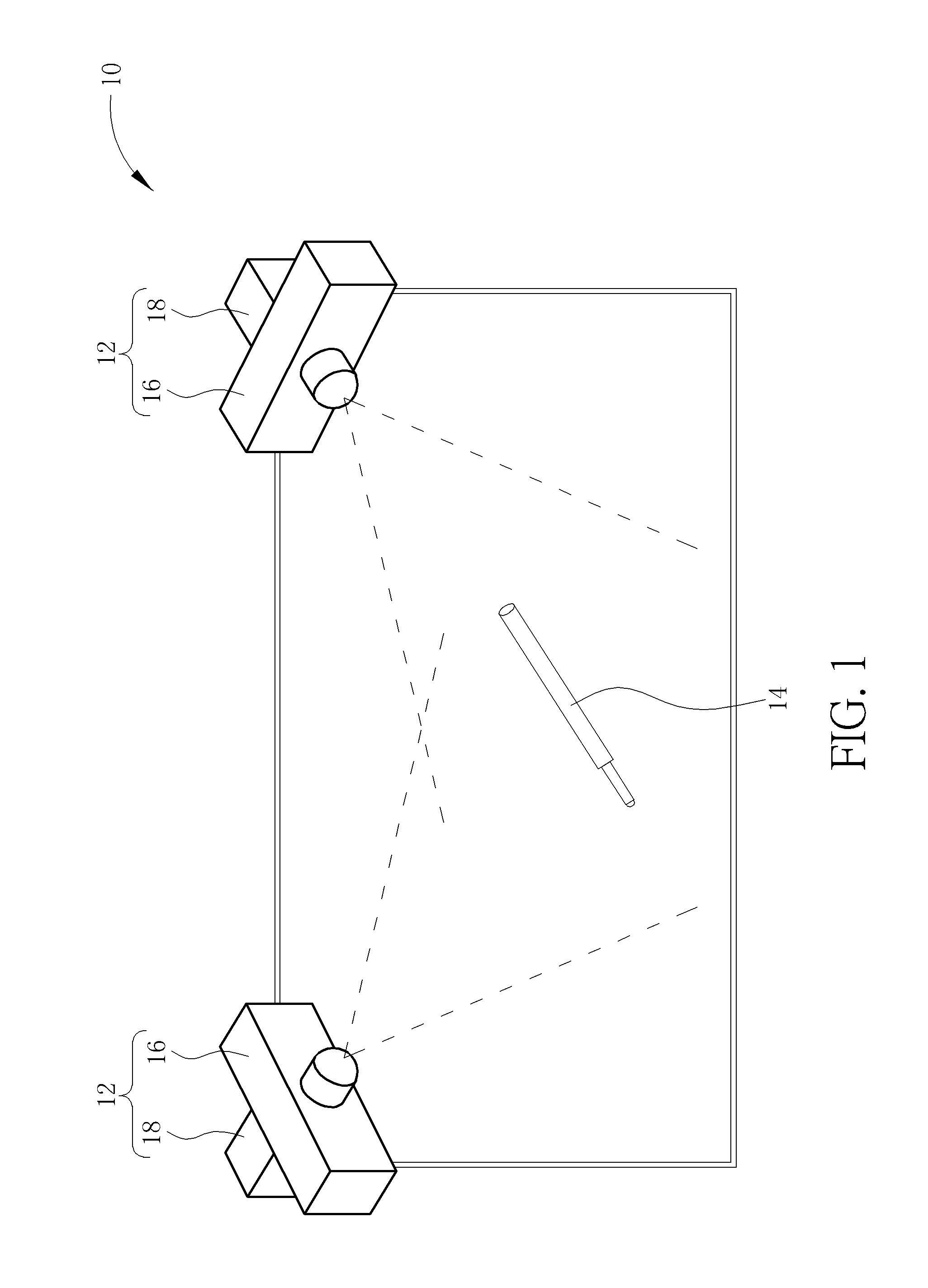
[0030]Please refer to FIG. 1. FIG. 1 is a diagram of an optical touch system 10 according to an embodiment of the present invention. The optical touch system 10 includes an optical detecting device 12 and an indicating light source 14. The optical detecting device 12 can detect and trace intensity and movement of an optical signal from the indicating light source 14, so as to determine a control command inputted by the user via the indicating light source 14. The indicating light source 14 can be a stylus with active luminosity function. The optical detecting device 12 includes an image detector 16 and a control unit 18. The image detector 16 is disposed on corners of the screen of the optical touch system 10, and faces toward the screen to acquire a continued image set. The screen may have no reflector, or further may be laid by optical absorbent for providing uniformly dark background. The image detector 16 can detect variation of the optical signal outputted by the indicating lig...
PUM
 Abstract
Description
Claims
Application Information
 - R&D
- Intellectual Property
- Life Sciences
- Materials
- Tech Scout
- Unparalleled Data Quality
- Higher Quality Content
- 60% Fewer Hallucinations
Browse by: Latest US Patents, China's latest patents, Technical Efficacy Thesaurus, Application Domain, Technology Topic, Popular Technical Reports.
© 2025 PatSnap. All rights reserved.Legal|Privacy policy|Modern Slavery Act Transparency Statement|Sitemap|About US| Contact US: help@patsnap.com


