
Automatic valve with interchangeable seat plate

a seat plate and automatic valve technology, applied in the direction of valve housing, hose connection, positive displacement liquid engine, etc., can solve the problems of inefficient sealing, automatic valves are subject to thermal stresses, time-consuming, etc., and achieve the effect of reducing compressor efficiency and convenient valve maintenan

Inactive Publication Date: 2014-11-20
NUOVO PIGNONE SPA
View PDF3 Cites 4 Cited by
  • Summary
  • Abstract
  • Description
  • Claims
  • Application Information

AI Technical Summary

Benefits of technology

The patent describes an automatic valve that uses non-metallic material for its movable sealing elements and a removable seat plate. This eliminates issues related to differential thermal expansion, such as gas leakage and reduced compressor efficiency. The use of non-planar sealing surfaces also results in efficient sealing and lower pressure losses. These two components will expand and contract at the same rate when exposed to temperature changes, ensuring their sealing efficiency. This design makes maintenance easier and reduces the need for re-machining worn valve seats. Overall, this automatic valve provides better sealing, reduced pressure losses, and easier maintenance.

Problems solved by technology

This operation requires removing the automatic ring valve from the compressor and is time consuming.
Similar drawbacks arise in automatic valves comprising a movable sealing element different from concentrically arranged sealing rings, for example a movable sealing plate.
Automatic valves are subject to thermal stresses due to the heat generated by friction and gas compression.
This can lead to inefficient sealing of the gas flow passages and consequent gas leakages, resulting in a reduction of the compressor efficiency, unless planar sealing surfaces are used.
The latter, on the other hand, are not entirely satisfactory from the point of view of an efficient sealing action.
Similar drawbacks arise if a movable sealing plate is used, e.g. provided with annular projections co-acting with annular seats on the valve seat.

Method used


Image

  • Automatic valve with interchangeable seat plate
  • Automatic valve with interchangeable seat plate
  • Automatic valve with interchangeable seat plate

Examples


Embodiment Construction

[0028]The following detailed description of the exemplary embodiments refers to the accompanying drawings. The same reference numbers in different drawings identify the same or similar elements. Additionally, the drawings are not necessarily drawn to scale. Also, the following detailed description does not limit the invention. Instead, the scope of the invention is defined by the appended claims.

[0029]Reference throughout the specification to “one embodiment” or “an embodiment” or “some embodiments” means that the particular feature, structure or characteristic described in connection with an embodiment is included in at least one embodiment of the subject matter disclosed. Thus, the appearance of the phrase “in one embodiment” or “in an embodiment” or “in some embodiments” in various places throughout the specification is not necessarily referring to the same embodiment(s). Further, the particular features, structures or characteristics may be combined in any suitable manner in one...


PUM


Abstract

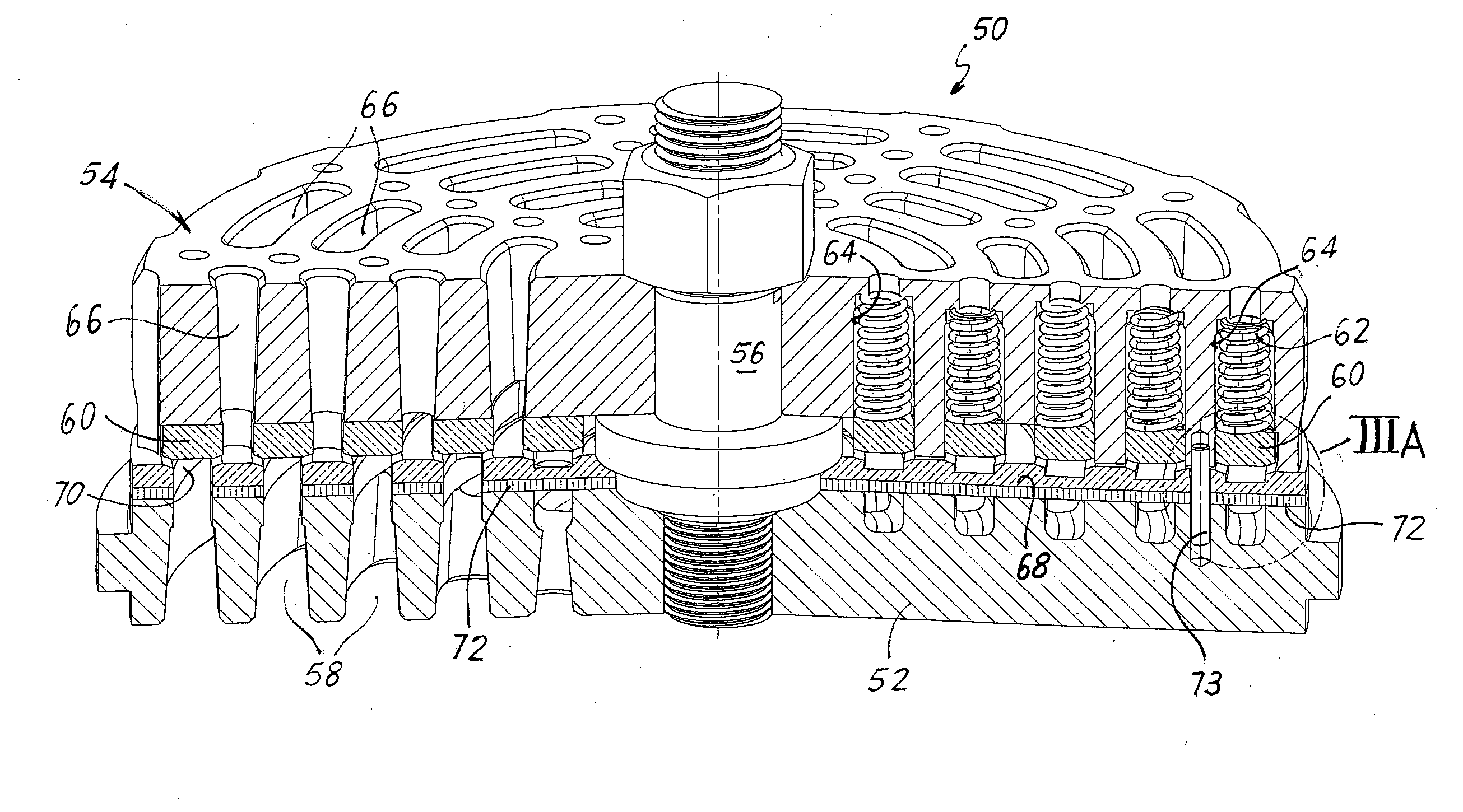
An automatic valve comprising a valve seat with first gas flow passages extending there through, and a valve guard having second gas flow passages extending there through. Sealing rings are arranged between the valve guard and the valve seat. A removable seat plate is removably connected to the valve seat and is provided with apertures matching with the first gas flow passages of the valve seat. The sealing rings are resiliently biased by resilient members against the removable seat plate to close the valve. The seat plate and the rings are made of non-metallic material.

Description

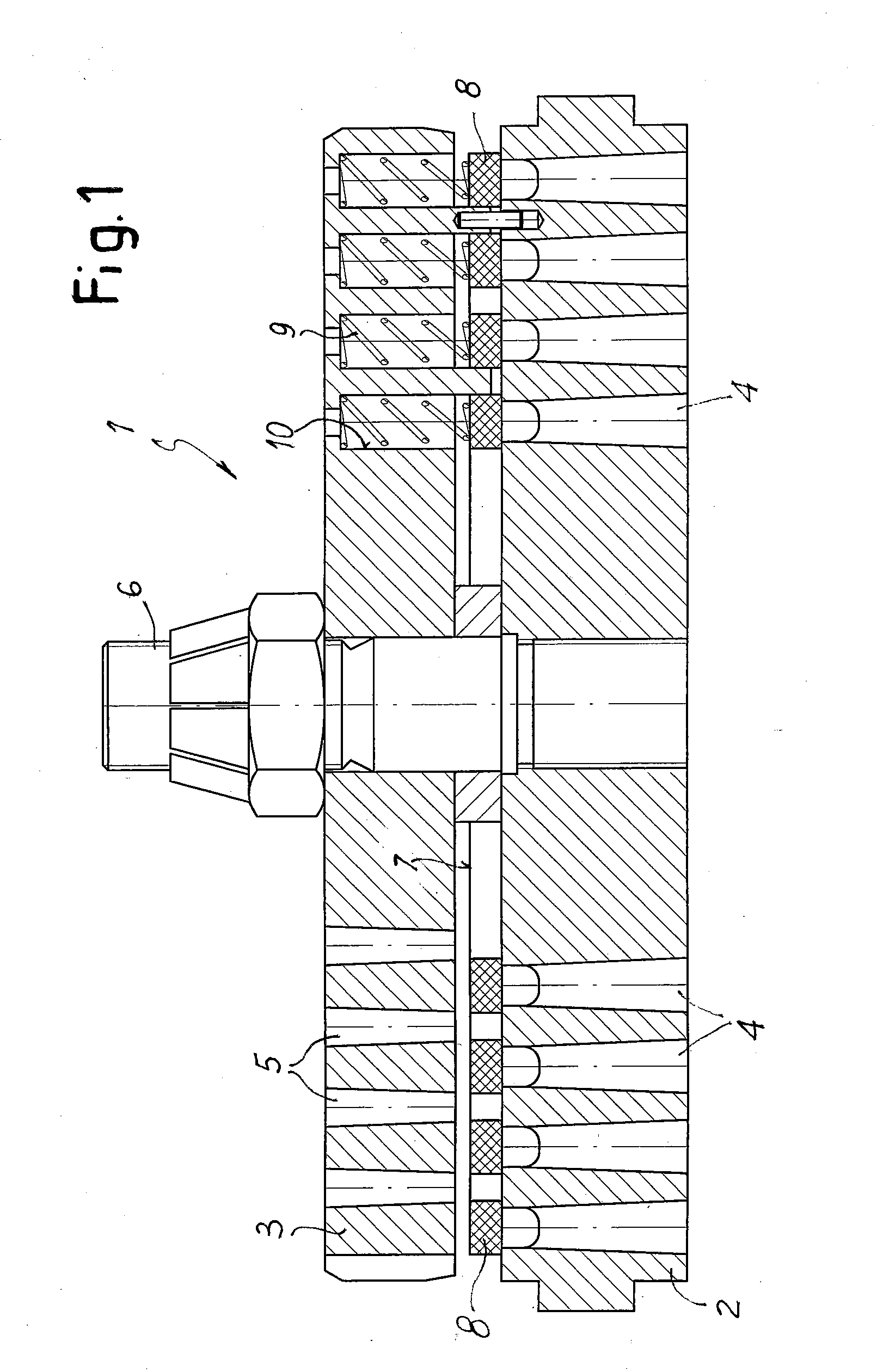
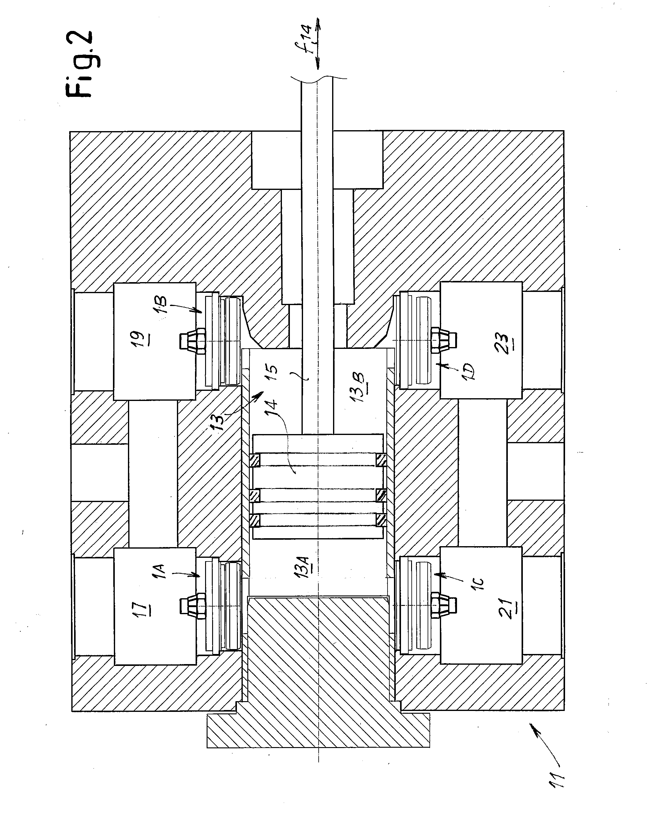
FIELD OF THE INVENTION[0001]The present disclosure relates to automatic valves, such as ring or annular valves. Some embodiments of the subject matter disclosed herein relate specifically to automatic ring or annular valves for reciprocating compressors.DESCRIPTION OF THE RELATED ART[0002]Automatic valves are commonly used for example in reciprocating compressors. Automatic valves are arranged on both the suction side as well as the discharge side of the compressor, to automatically open and close the suction port and discharge port of the compressor under the control of the pressure inside the compressor cylinder.[0003]An exemplary embodiment of an automatic ring valve of the prior art is illustrated in FIG. 1. The automatic ring valve 1 comprises a valve seat 2 and a valve guard 3. The valve seat is provided with circumferentially arranged gas flow passages 4 extending through the valve seat 2. The valve guard 3 is in tum provided with gas flow passages 5. A central screw 6 connec...

Claims


Application Information

Patent Timeline
Patent Type & Authority Applications(United States)
IPC IPC(8): F16K25/00F16K15/08
CPCF16K15/08F16K25/00F04B39/102F04B39/1053Y10T137/7062F04B39/10
Inventor BABBINI, ALBERTOBAGAGLI, RICCARDOTOGNARELLI, LEONARDOPRATELLI, GUIDO
Owner NUOVO PIGNONE SPA
Learn More