
Electromagnetic coil system for driving control of micro-robot

a technology of electric coils and micro-robots, which is applied in the direction of programmed manipulators, applications, manufacturing tools, etc., can solve the problems of reducing the practical use of the system, a large volume, and a large volume of the coil structure, so as to improve the capacity of efficient use of space, simplify the structure of the complex coil, and reduce the volume

Active Publication Date: 2014-11-13
KOREA INST OF SCI & TECH
View PDF0 Cites 17 Cited by
  • Summary
  • Abstract
  • Description
  • Claims
  • Application Information

AI Technical Summary

Benefits of technology

The present disclosure describes a two-dimensional electromagnetic coil system that can provide a larger workspace and performance, while reducing volume and power consumption compared to existing systems. The system uses Helmholtz coils to control the position and direction of micro-robots, making efficient use of space. The system also performs pre-calculations on electric current and applies only the necessary amount of power to each coil, reducing power consumption compared to conventional systems. The system can be used in various medical robot applications, improving technology in this field.

Problems solved by technology

However, since the conventional electromagnetic coil system uses a total of four pairs of coils, i.e. two pairs of Helmholtz coils and two pairs of Maxwell coils, it has a disadvantage in that it has a large volume and a lot of power consumption.
Further, due to this disadvantage, above all, in the application to a medical field, due to the large volume and the lot of power consumption of the two-dimensional electromagnetic coil system for controlling driving of the micro-robot compared to the workspace of the micro-robot, there is a problem in that the practical use of the system is reduced.

Method used


Image

  • Electromagnetic coil system for driving control of micro-robot
  • Electromagnetic coil system for driving control of micro-robot
  • Electromagnetic coil system for driving control of micro-robot

Examples


Embodiment Construction

[0028]Hereinafter, exemplary embodiments of the present disclosure will be described in further detail with reference to the accompanying drawings.

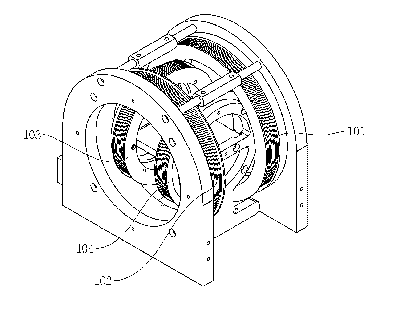
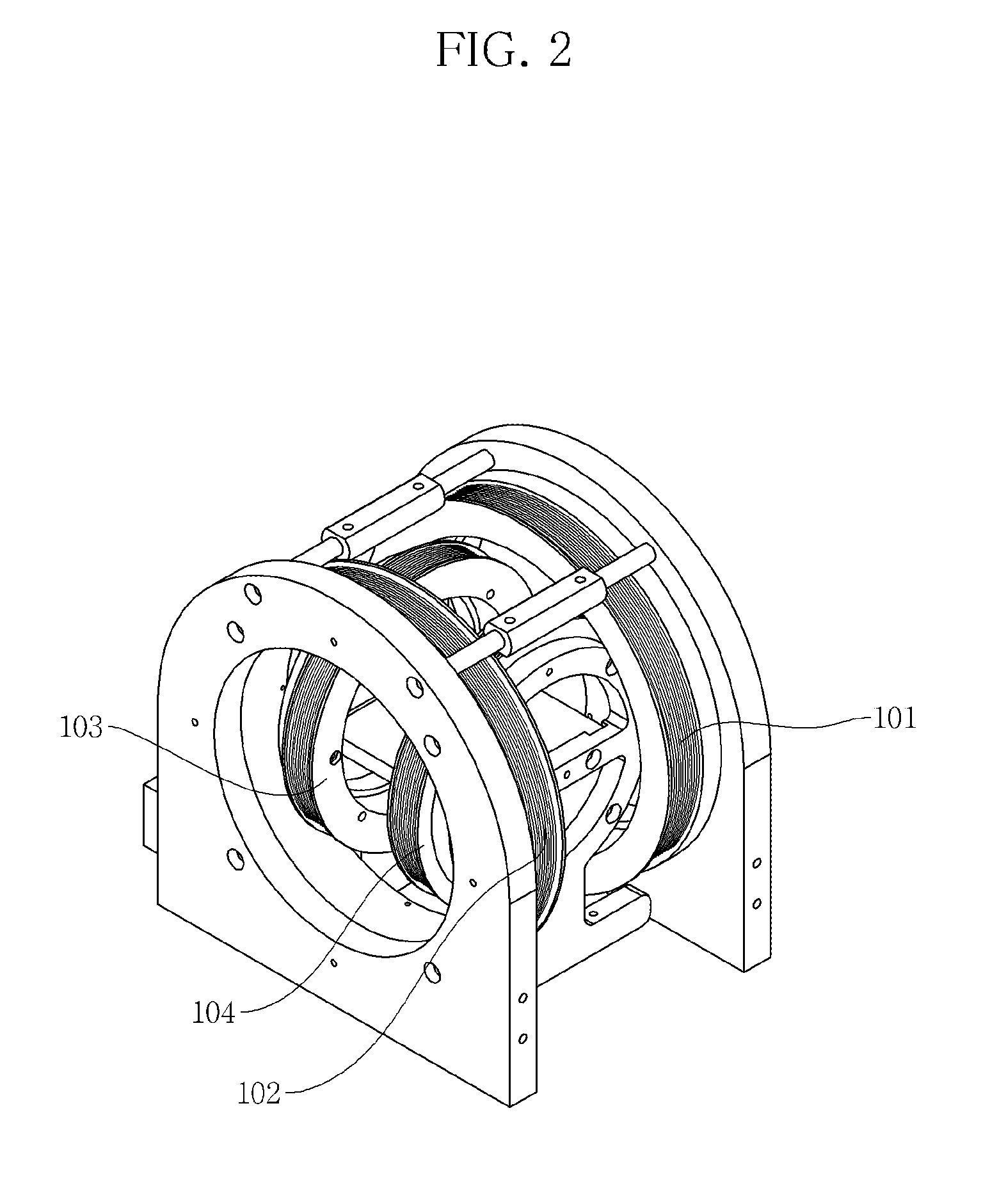
[0029]FIG. 2 is a perspective view showing an electromagnetic coil system according to an exemplary embodiment of the present disclosure. FIG. 3 is a front view of the electromagnetic coil system of FIG. 2. FIG. 4 is a top plan view of the electromagnetic coil system of FIG. 2. FIG. 5 is a view for describing a driving principle of the inventive electromagnetic coil system.

[0030]Referring to FIGS. 2 to 5, an electromagnetic coil system for driving control of a micro-robot 109 according to an exemplary embodiment of the present disclosure includes an electromagnetic field generating coil unit 100 installed around a workspace of the micro-robot 109, a position recognition system 106 that recognizes a position of the micro-robot 109, a controller 107 that controls electric currents so as to control turnabout and movement of the micro-robot 1...


PUM


Abstract

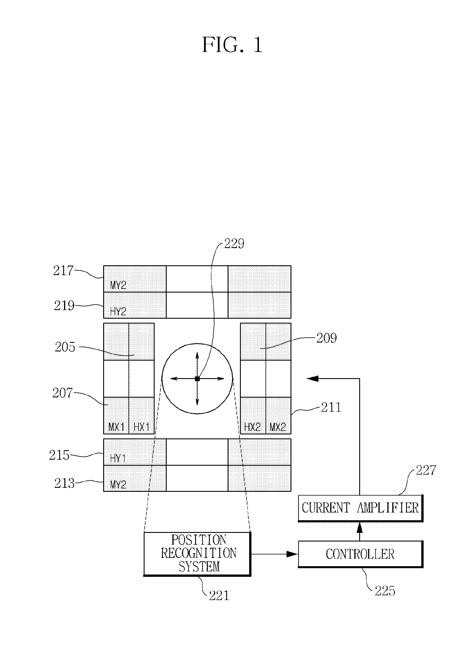
An electromagnetic coil system for driving control of a micro-robot includes pairs of X-axis and Y-axis Helmholtz coils whose winding central axes are placed on an X axis and Y axis respectively, a position recognition system that detects a position and direction of the micro-robot in a workspace, a controller that controls an amount of supply of electric currents flowing to the X-axis or Y-axis Helmholtz coils in order to control movement of the micro-robot based on information about the movement of the micro-robot and previously input information about a path of the micro-robot, and a current amplifier that supplies the electric currents to the respective Helmholtz coils. The pairs of X-axis and Y-axis Helmholtz coils are disposed so as to face each other, and the X-axis Helmholtz coils and the Y-axis Helmholtz coils are vertically crossed and installed so as to form the workspace of the micro-robot.

Description

CROSS-REFERENCE TO RELATED APPLICATION[0001]This application claims priority to Korean Patent Application No. 10-2013-0052043, filed on May 8, 2013, and all the benefits accruing therefrom under 35 U.S.C. §119, the contents of which in its entirety are herein incorporated by reference.BACKGROUND[0002]1. Field[0003]Exemplary embodiments relate to an electromagnetic coil system for driving control of a micro-robot, and more particularly to an electromagnetic coil system that structurally requires fewer electromagnetic coils compared to an existing electromagnetic coil system for which a pair of Helmholtz coils and a pair of Maxwell coils are required, so that it can reduce a size thereof to increase space efficiency and reduce power consumption thereof to increase power efficiency.[0004]2. Description of the Related Art[0005]In general, existing micro-robot electromagnetic driving systems are made up of an electromagnet coil using a Helmholtz coil and a Maxwell coil, and include a pow...

Claims


Application Information

Patent Timeline
IPC IPC(8): B25J9/12H01F38/14
CPCB25J9/12H01F38/14Y10S901/23A61B1/00158H01F7/20B25J7/00B25J13/00
Inventor KIM, SEUNG-JONGKIM, JIN SOOYOO, JEONGHOON
Owner KOREA INST OF SCI & TECH
Learn More