
Prosthesis component

a technology of femoral head and component, applied in the field of prosthesis components, can solve the problems of limited range of motion, and increased articulating surface area, and achieve the effect of reducing the risk of wear and tear

Inactive Publication Date: 2014-10-30
BIOMET UK HEALTHCARE
View PDF7 Cites 3 Cited by
  • Summary
  • Abstract
  • Description
  • Claims
  • Application Information

AI Technical Summary

Benefits of technology

The patent is about a bearing pair that engages each other. One of the bearings may use boundary lubrication. The bearing surfaces are made of ceramic, and one of them is reinforced with carbon fibres. The overall shell has openings for fixation. The technical effect of this is the creation of a bearing pair that can withstand high temperatures and loads with high precision.

Problems solved by technology

This leads to the use of smaller diameter femoral head components, which have favourable wear characteristics but suffer from a limited range of motion.
In contrast, in order to promote joint stability it is desirable to use a large diameter femoral head component, which has the additional benefit of a better range of patient motion but results in an increase in the articulating surface area, and hence risk of wear damage.
While the double mobility type hip prosthesis has experienced good results, there remain some disadvantages to the system.
The larger articulation of polyethylene liner against metal shell is excellent for stability, but it does not provide the best wear characteristics.
Some prostheses have experimented with alternative metal alloys and material coatings for the shell to address the wear characteristics, but in the main this issue has been ignored in existing devices as the articulation is only engaged at extremes of motion and the wear performance of the articulation has not been considered a priority.
Fixation is another area where difficulties can arise with a double mobility prosthesis.
This is acceptable in many cases but does not offer alternatives for patients with a high level of degradation of the acetabular bone tissue.
In the case of a double mobility prosthesis the liner must articulate against the shell, and so the inclusion of bone screws can only be achieved by increasing the degree of modularity within the device, adding an extra liner between the shell and the articulating liner.
However, the inclusion of the extra liner reduces the space available for the femoral head, meaning the extra fixation comes at the expense of a reduced range of motion.

Method used


Image

  • Prosthesis component
  • Prosthesis component
  • Prosthesis component

Examples


Embodiment Construction

[0034]The present invention relates to a double mobility acetabular prosthesis component and cooperating femoral head prosthesis component that together provide a hip prosthesis having ceramic on ceramic and ceramic on carbon fibre reinforced polymer articulations.

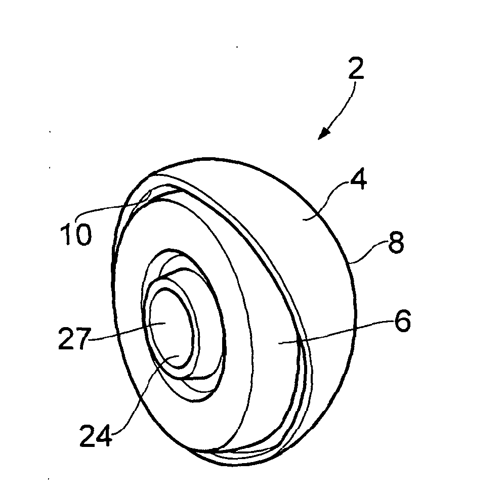
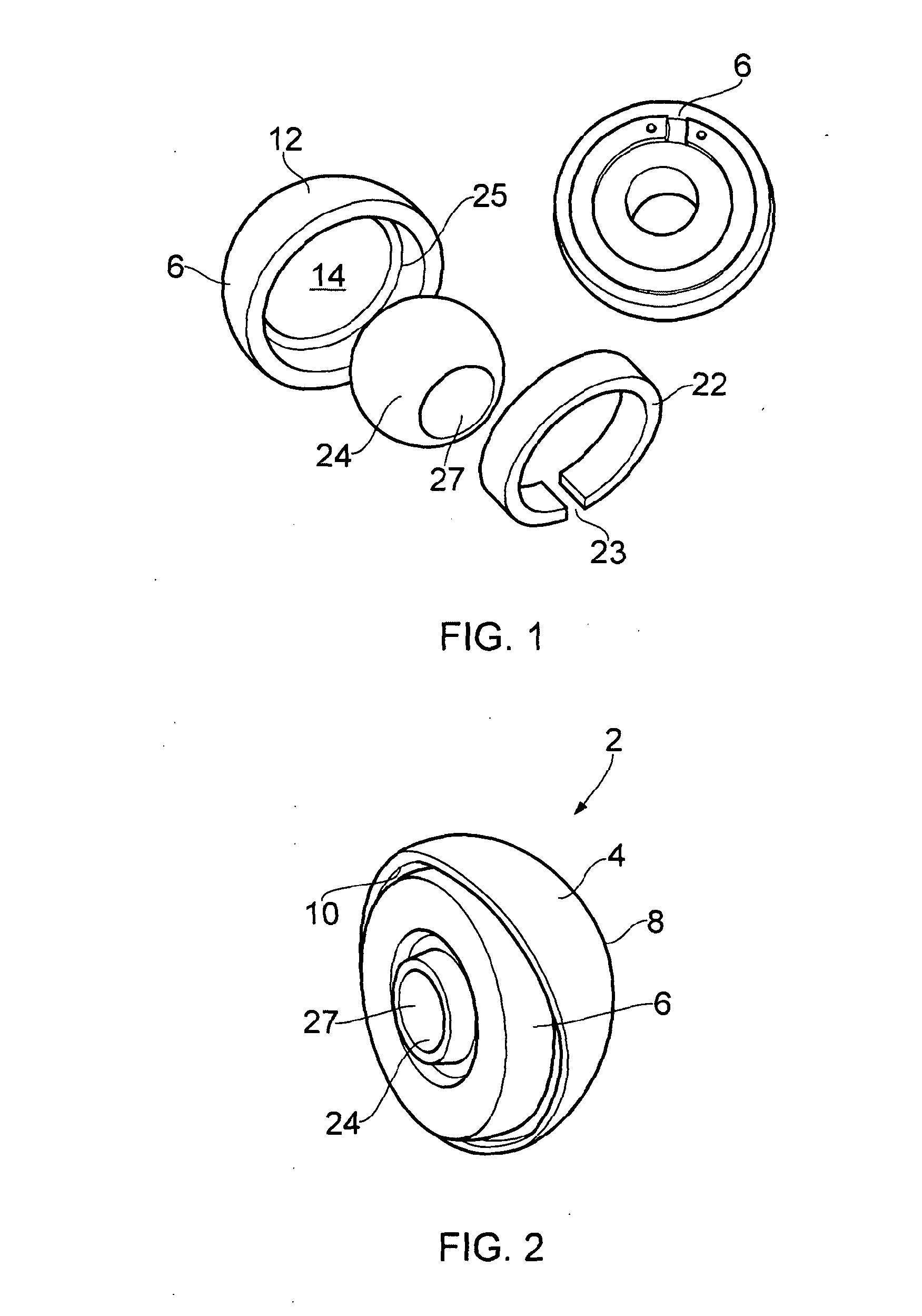
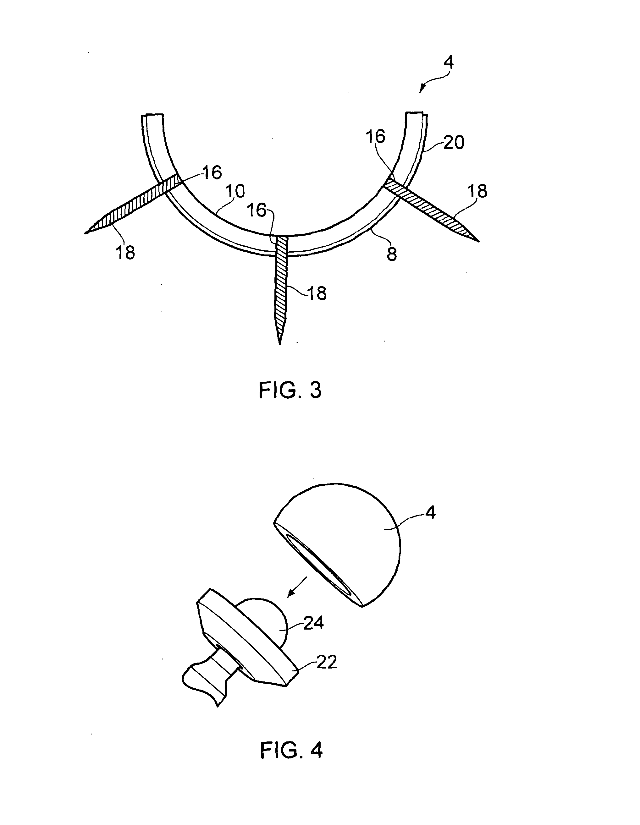
[0035]With reference to FIGS. 1 and 2, an acetabular prosthesis component 2 in accordance with an embodiment of the present invention comprises a shell 4 and a liner 6. The shell 4 is substantially hemispherical and is formed from a carbon fibre reinforced polymer material. According to the embodiment of the invention described below, the shell 4 is formed from carbon fibre reinforced polyether ether ketone (CFR-PEEK), however it will be appreciated that other fibre reinforced polymer materials may be considered. A carbon fibre reinforced polymer material such as CFR-PEEK provides a low wear bearing surface, as well as offering an alternative to metal bearing surfaces, concerns over which have been expressed in the literat...


PUM


Abstract

A prosthesis component 2 is disclosed, the component comprising a shell (2) formed form a carbon fibre reinforced polymer material and having an inner bearing surface (10); and a liner (6) formed from a ceramic material and having an outer bearing surface(12); wherein the liner (6) is received in an articulating manner within the shell (4). A hip replacement prosthesis is also disclosed, the hip replacement prosthesis comprising a prosthesis component (2) as disclosed and a femoral head prosthesis component (24), the femoral head prosthesis component being formed from a ceramic material.

Description

[0001]The present invention relates to a prosthesis component, and particularly to a prosthesis component having a shell and articulating liner.BACKGROUND[0002]It is known to replace some or all of a natural bone joint that has become damaged or diseased with prosthetic components. For example, a natural hip joint that has become degraded may be replaced with an artificial joint comprising a prosthetic acetabular component which is implanted into the patient's acetabulum, and a prosthetic femoral head component which is implanted into the patient's femur and articulates with the acetabular component. A prosthetic joint of this type is known as a total hp replacement (THR).[0003]Various types of THR exist and are well known in the art. The different types of prosthesis take different approaches to balancing the competing requirements of reducing wear in the joint, maintaining stability of the joint, increasing patient range of motion, and many other factors. Reducing wear on the pros...

Claims


Application Information

Patent Timeline
Patent Type & Authority Applications(United States)
IPC IPC(8): A61F2/34
CPCA61F2002/3275A61F2/34A61F2002/3208A61F2/30965A61F2/32A61F2002/3233A61F2002/3401A61F2002/3241A61L27/18
Inventor BIGSBY, ROBERT JOHN ANDREWKHAN, MOHAMMED IMRAN
Owner BIOMET UK HEALTHCARE
Learn More