
LED lighting control system

Active Publication Date: 2014-10-30
NULSOM
View PDF2 Cites 33 Cited by
  • Summary
  • Abstract
  • Description
  • Claims
  • Application Information

AI Technical Summary

Benefits of technology

The LED lighting control system described in this patent text has several technical effects. Firstly, it can easily measure voltage or current to detect any faulty LED modules. Secondly, it can control multiple lighting modules simultaneously without any delays. Thirdly, it allows different communication protocols to communicate with a central control device, and can automatically identify faulty LED modules. Lastly, it uses comparators instead of analog-to-digital converters, simplifying the structure and reducing manufacturing costs. Overall, this system provides improved efficiency, control, and monitoring of LED lighting systems.

Problems solved by technology

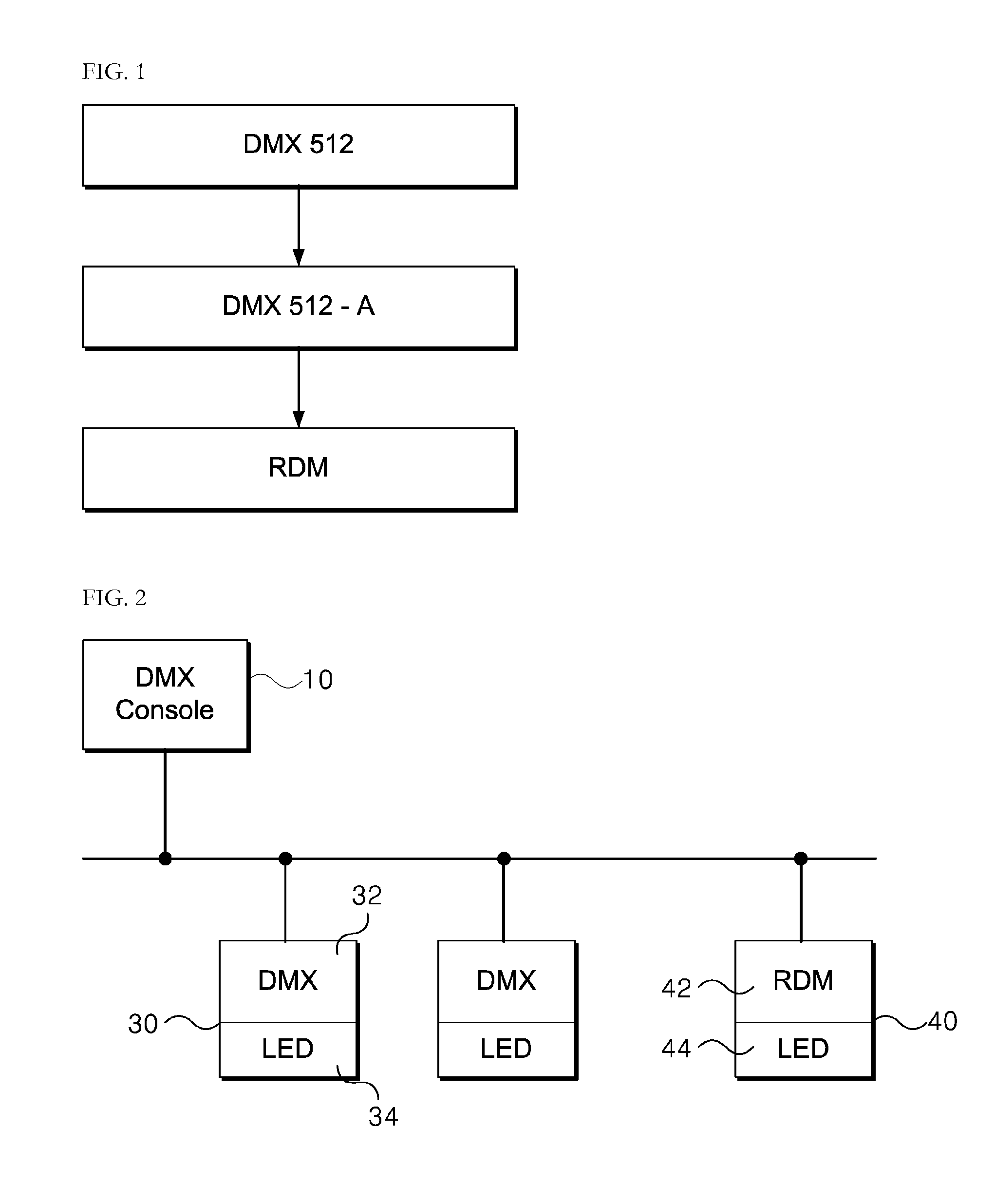
Devices used in a lighting control system, such as a central control device or a light-emitting diode (LED) driver may not be compatible with one another if they use different communication protocols.
The replacement of unidirectional communication protocol-based lighting modules with bidirectional communication protocol-based lighting modules may be highly costly, and thus, a lighting system capable of allowing existing lighting modules to be gradually replaced with new lighting modules is needed.
A lighting module, particularly, a light-emitting diode (LED) lighting module, generally includes a considerable number of LEDs, and may thus make it difficult to detect any faulty LED therefrom.
That is, a predetermined channel to which the control signal is to be transmitted may receive the control signal only after the transmission of the signals to the 511 channels, thereby making it difficult to control a lighting system in real time.

Method used


Image

  • LED lighting control system
  • LED lighting control system
  • LED lighting control system

Examples


Embodiment Construction

[0027]The following detailed description is provided to assist the reader in gaining a comprehensive understanding of the methods, apparatuses, and / or systems described herein. However, various changes, modifications, and equivalents of the systems, apparatuses and / or methods described herein will be apparent to one of ordinary skill in the art. Also, descriptions of functions and constructions that are well known to one of ordinary skill in the art may be omitted for increased clarity and conciseness.

[0028]It will be understood that, although the terms “first”, “second”, etc. may be used herein to describe various elements, these elements should not be limited by these terms. These terms are only used to distinguish one element from another. For example, a first element could be termed a second element, and, similarly, a second element could be termed a first element without departing from the teachings of the disclosure.

[0029]The terms “module” and “unit” used to signify component...


PUM


Abstract

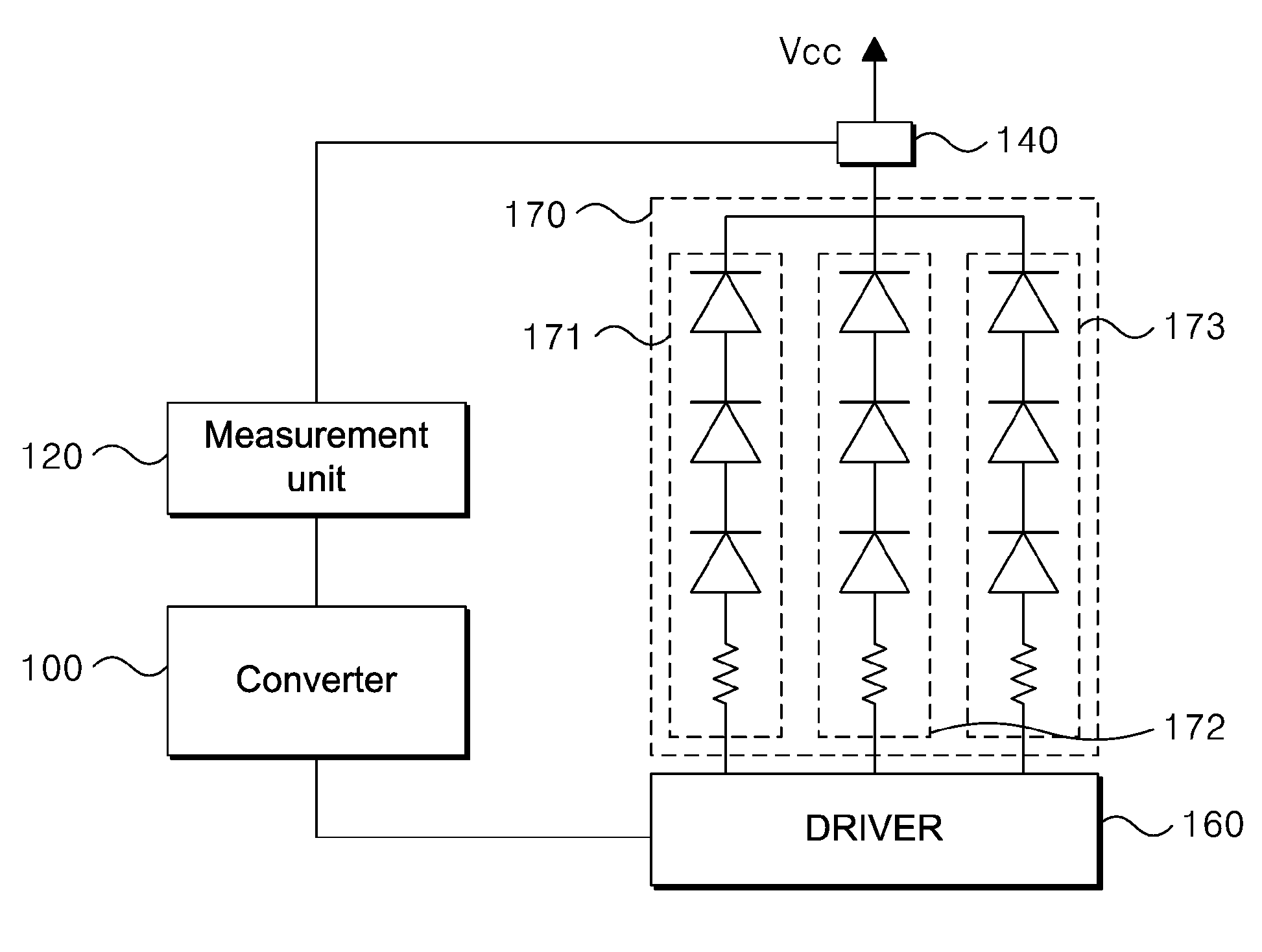
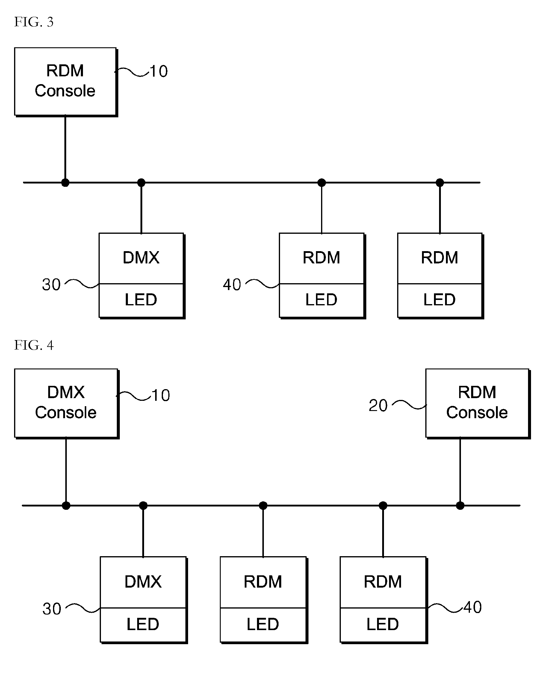
Provided is a light-emitting diode (LED) lighting control system, and more particularly, an LED lighting control system capable of controlling not only a lighting module supporting unidirectional communication, but also a lighting module supporting bidirectional communication, notifying a central control device of any fault or failure in the unidirectional communication protocol-based lighting module, and removing any delays in lighting control that may be caused by limited communication lines. The LED lighting system includes: a central control device configured to transmit a lighting control signal, which is based on a unidirectional or bidirectional communication protocol, to a plurality of channels; a converter configured to be connected to one of the channels and determine whether the lighting control signal is based on the unidirectional communication protocol or the bidirectional communication protocol in response to the lighting control signal including channel information of the converter; and a driver configured to be connected to the converter and control the operation of a plurality of LED modules in accordance with a control data signal transmitted by the converter.

Description

[0001]This application claims priority from Korean Patent Application No. 10-200X-000000 filed on Month Day, 200X in the Korean Intellectual Property Office, the disclosure of which is incorporated herein by reference in its entirety.BACKGROUND[0002]1. Field of the Invention[0003]Embodiments relate to a light-emitting diode (LED) control system, and more particularly, to an LED lighting control system capable of controlling not only a lighting module supporting unidirectional communication, but also a lighting module supporting bidirectional communication, notifying a central control device of any fault or failure in the unidirectional communication protocol-based lighting module, and removing any delays in lighting control that may be caused by limited communication lines.[0004]2. Description of the Related Art[0005]The Digital Addressable Lighting Interface (DALI) standard has been used for illumination control systems. The DALI standard enables a digital communication lighting co...

Claims


Application Information

Patent Timeline
IPC IPC(8): H05B33/08H05B44/00
CPCH05B33/0842H05B47/175H05B45/30H05B45/325H05B45/40H05B45/10
Inventor LEE, CHANG-HOON
Owner NULSOM
Learn More