
Method of Real Time Monitoring of Well Operations Using Self-Sensing Treatment Fluids

a treatment fluid and well technology, applied in survey, wellbore/well accessories, construction, etc., can solve problems such as cracking and/or disintegration of cement sheaths, expansion and/or contraction of radial and longitudinal pipes, and flow and control lines within wells

Inactive Publication Date: 2014-10-30
BAKER HUGHES INC
View PDF23 Cites 23 Cited by
  • Summary
  • Abstract
  • Description
  • Claims
  • Application Information

AI Technical Summary

Benefits of technology

This patent describes a method for monitoring the conditions of a drilling fluid or cement in a wellbore. This is done by pumping a special fluid containing a piezoelectric or piezoresistive material into the wellbore and measuring the electrical resistivity of the fluid. This allows for real-time monitoring of downhole conditions, cement hardening, and the strengthening process of the cement. The method can also be used to evaluate the stability of the cement or to monitor the returns of drilling mud. Overall, this invention provides a way to better monitor the behavior of drilling fluids and cements in wellbore applications.

Problems solved by technology

Insufficient mud return to the surface may cause problems with flow and control lines within the well.
In addition, variations in temperature and internal pressure of the wellbore pipe string may result in radial and longitudinal pipe expansion and / or contraction.
Such stresses lead to cracking and / or disintegration of the cement sheath.
Due to the long duration of the hardening process, prior to reaching the final strength, the chemically active material undergoes many complicated physical and chemical processes, which can essentially affect its physical properties.
It is recognized that any change, deviation and non-observance of the technological regulations during preparation of the chemically active material, such as ready-mixed or pre-cast concrete, may irreversibly reduce the properties (e.g., strength) of the final product.
During hardening of the cement mix to the cement sheath, problems may arise which weaken the structure of the cement sheath.
One such problem is gas channeling.
It is in this transition stage that the hardening cement mix is susceptible to formation gas entering into the cement sheath.
Another common problem encountered during hardening of the cement is the loss of liquid fluid from the slurry into porous low pressure zones in the formation surrounding the well annulus.
Fluid (liquid and / or gas) loss is undesirable since it can result in dehydration of the cementitious slurry.
In addition, it may cause the formation of thick filter cakes of cement solids.
In addition, fluid loss can damage sensitive formations.
In addition, there is an increasing need to prevent compromises to the well which may be attributed to the lack of mud and cement returns which cause problems with flow and control lines.

Method used


Image

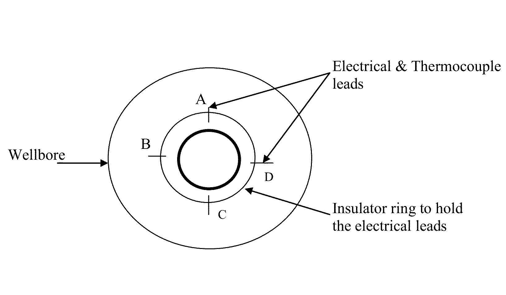
  • Method of Real Time Monitoring of Well Operations Using Self-Sensing Treatment Fluids
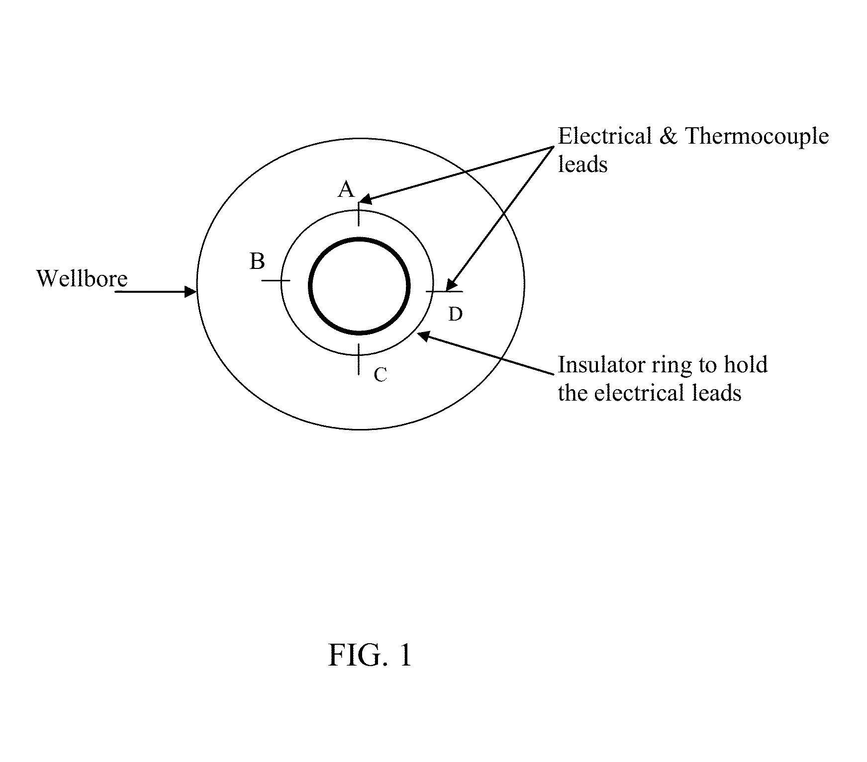
  • Method of Real Time Monitoring of Well Operations Using Self-Sensing Treatment Fluids
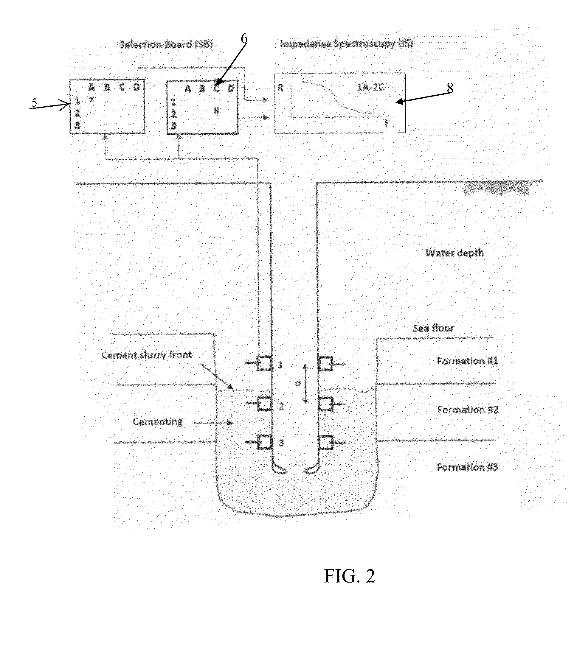
  • Method of Real Time Monitoring of Well Operations Using Self-Sensing Treatment Fluids

Examples


Embodiment Construction

[0029]Characteristics and advantages of the present disclosure and additional features and benefits will be readily apparent to those skilled in the art upon consideration of the following detailed description of exemplary embodiments of the present disclosure and referring to the accompanying figures. It should be understood that the description herein and appended drawings, being of example embodiments, are not intended to limit the claims of this patent or any patent or patent application claiming priority hereto. On the contrary, the intention is to cover all modifications, equivalents and alternatives falling within the spirit and scope of the claims. Many changes may be made to the particular embodiments and details disclosed herein without departing from such spirit and scope.

[0030]In showing and describing embodiments in the appended figures, common or similar elements may be referenced with like or identical reference numerals or are apparent from the figures and / or the des...


PUM


Abstract

Downhole conditions in a wellbore may be monitored in real time by pumping into the well a sensing treatment fluid which includes a piezoelectric or piezoresistive material and measuring changes in electrical resistivity within the wellbore. The monitoring in real time of the piezoelectric or piezoresistive material enhances the integrity of the wellbore during the setting of the treatment fluid as well as during the lifetime of the well.

Description

[0001]This application claims the benefit of U.S. patent application serial no. 61 / 817,771, filed on Apr. 30, 2013, which is herein incorporated by reference.FIELD OF THE DISCLOSURE[0002]Downhole conditions of a self-sensing treatment fluid may be monitored in real time by incorporating into the fluid a piezoelectric or piezoresistive material.BACKGROUND[0003]During construction of a well penetrating a subterranean formation, a rotary drill is typically used to bore through the subterranean formation to form a wellbore. In a typical drilling operation, a drilling mud is injected under pressure through the drill string. The mud returns to the surface through the drill string-borehole annulus. Once returned to the surface, the drilling mud contains cuttings from the drill bit. Although most large cuttings are removed at the surface prior to recirculating the fluid, smaller sized particles remain suspended within the drilling fluid. Insufficient mud return to the surface may cause prob...

Claims


Application Information

Patent Timeline
Patent Type & Authority Applications(United States)
IPC IPC(8): E21B33/14
CPCE21B33/14E21B33/13E21B47/00E21B47/07C09K8/42E21B47/005
Inventor MARTIN, ROBERT S.NARVAEZ, GUIDO GUSTAVOQU, QIITSKOVICH, GREGORY B.
Owner BAKER HUGHES INC
Learn More