Electronic device and method for resuming from hibernation for the same
a technology of electronic devices and hibernation, applied in the field of electronic devices, can solve the problems of inconvenient whole operation behavior, unsatisfactory user experience, and use of electronic devices, and achieve the effect of convenient and user-friendly, improving and optimizing the operation flow
- Summary
- Abstract
- Description
- Claims
- Application Information
AI Technical Summary
Benefits of technology
Problems solved by technology
Method used
Image
Examples
second embodiment
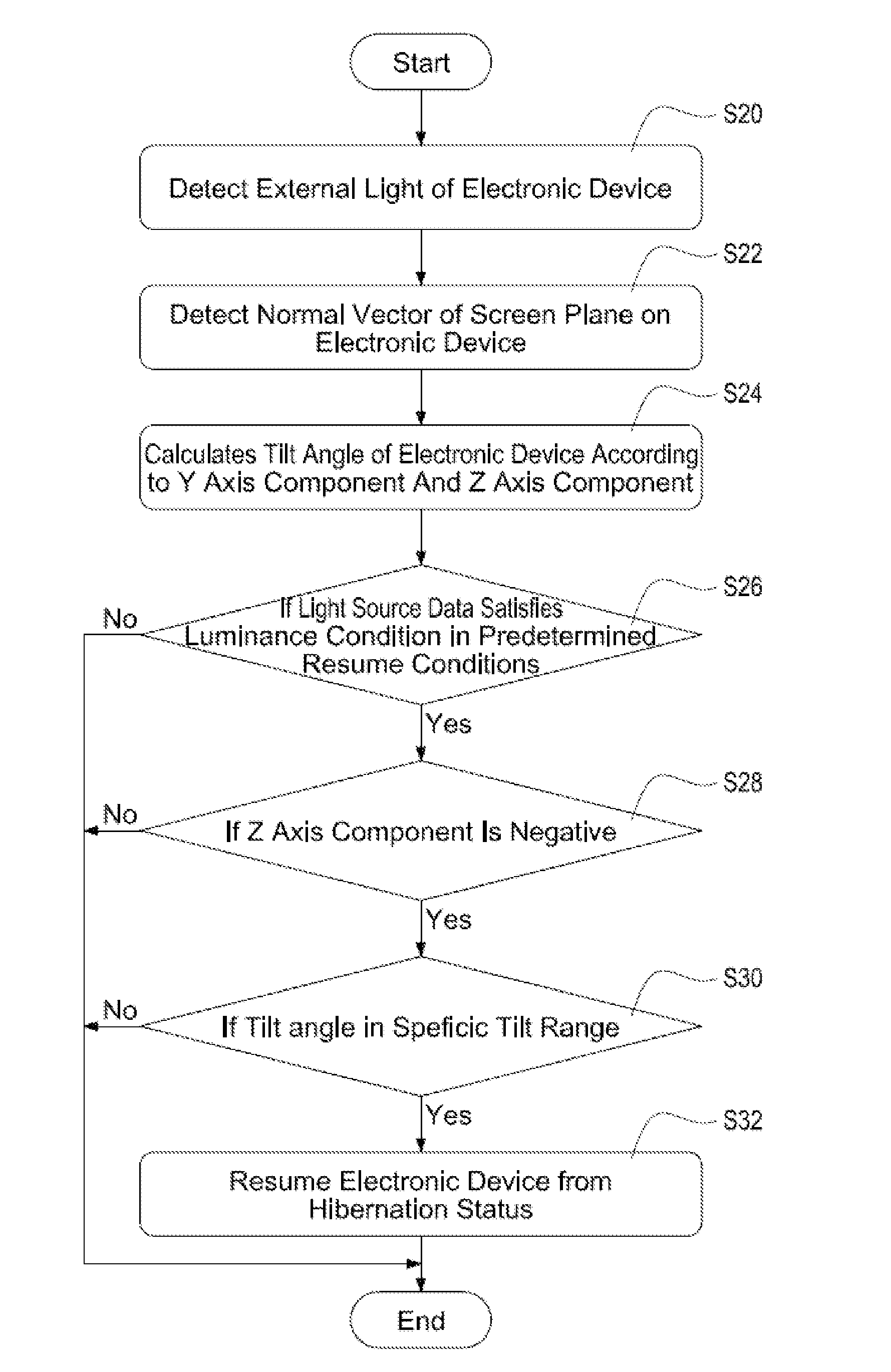
[0042]FIG. 7 is a resuming flowchart according to the present invention. In the embodiment, a G-sensor is used as an example of the tilt sensing component 33, the sensing mechanism of the G-sensor is different from that of a gyro (detailed in the following).
[0043]As shown in the FIG. 7, when the electronic device 3 is in the hibernation status, the external light of the electronic device 3 is detected via the light sensing component 32 (step S20), for attaining the above mentioned light source data according to the detected results. Next, the normal vector of the plane of the screen 31 on the electronic device 3 is detected via the tilt sensing component 33 (the G-sensor in the embodiment) (step S22). The normal vector comprises an x axis component, a y axis component and a z axis component.
[0044]FIG. 8 and FIG. 9 are respectively normal vector schematic diagrams according to the first and the second embodiment of the present invention. As shown in the diagram, the above mentioned n...
first embodiment
[0052]FIG. 10 is a schematic diagram of the predetermined resuming conditions according to the present invention. In the embodiment, the predetermined resuming conditions 36 are set by the user 2, or are predetermined. For example, in FIG. 10, the predetermined resuming conditions 36 comprises the above specific tilt range 361, and also comprises a predetermined time range 362 as well as a displacement threshold value 363 (detailed in the following). Thus, the processing unit 34 is allowed to determine if the electronic device 3 resumes according to the light source data and the tilt data, further the processing unit 34 can determine if the electronic device 3 resumes from the hibernation status according to the operated time of the electronic device 3 by the user 2, and the displacement value of the electronic device 3.
[0053]As mentioned above, under the normal operating status, the screen 31 of the electronic device 3 faces up (the z axis component is negative). Nonetheless, under...
third embodiment
[0054]Refer to FIG. 11 and FIG. 12, FIG. 11 is the third status schematic diagram according to the present invention, and FIG. 12 is a resuming flowchart according to the present invention. As shown in FIG. 11, when the electronic device 3 is held by the user 2 with the screen 31 facing down, the processing unit 34 determines that the z axis component of the electronic device 3 is positive. Accordingly, the processing unit 34 has to make determination based on the embodiment shown in FIG. 12 such that the user 2 is allowed to normally operate the electronic device 3 under the circumstance.
[0055]As shown in FIG. 12, when the electronic device 3 is in the hibernation status, the external light of the electronic device 3 is detected by the light sensing component 32 (step S40), for attaining the above mentioned light source data according to the detected results. Next, the normal vector of the plane of the screen 31 on the electronic device 3 is detected by the tilt sensing component 3...
PUM
 Abstract
Description
Claims
Application Information
 - R&D
- Intellectual Property
- Life Sciences
- Materials
- Tech Scout
- Unparalleled Data Quality
- Higher Quality Content
- 60% Fewer Hallucinations
Browse by: Latest US Patents, China's latest patents, Technical Efficacy Thesaurus, Application Domain, Technology Topic, Popular Technical Reports.
© 2025 PatSnap. All rights reserved.Legal|Privacy policy|Modern Slavery Act Transparency Statement|Sitemap|About US| Contact US: help@patsnap.com


