
Bidirectional parallel optical transceiver module and a method for bidirectionally communicating optical signals over an optical link

a parallel optical transceiver and optical link technology, applied in electromagnetic transceivers, optical elements, instruments, etc., can solve the problems of significant addition of costs associated with such links, limitation of the extent to which currently available technologies can be used to improve the bandwidth of optical fiber links, and difficulty in scaling such links to achieve increasingly higher bandwidths

Active Publication Date: 2014-10-23
AVAGO TECH INT SALES PTE LTD
View PDF11 Cites 32 Cited by
  • Summary
  • Abstract
  • Description
  • Claims
  • Application Information

AI Technical Summary

Benefits of technology

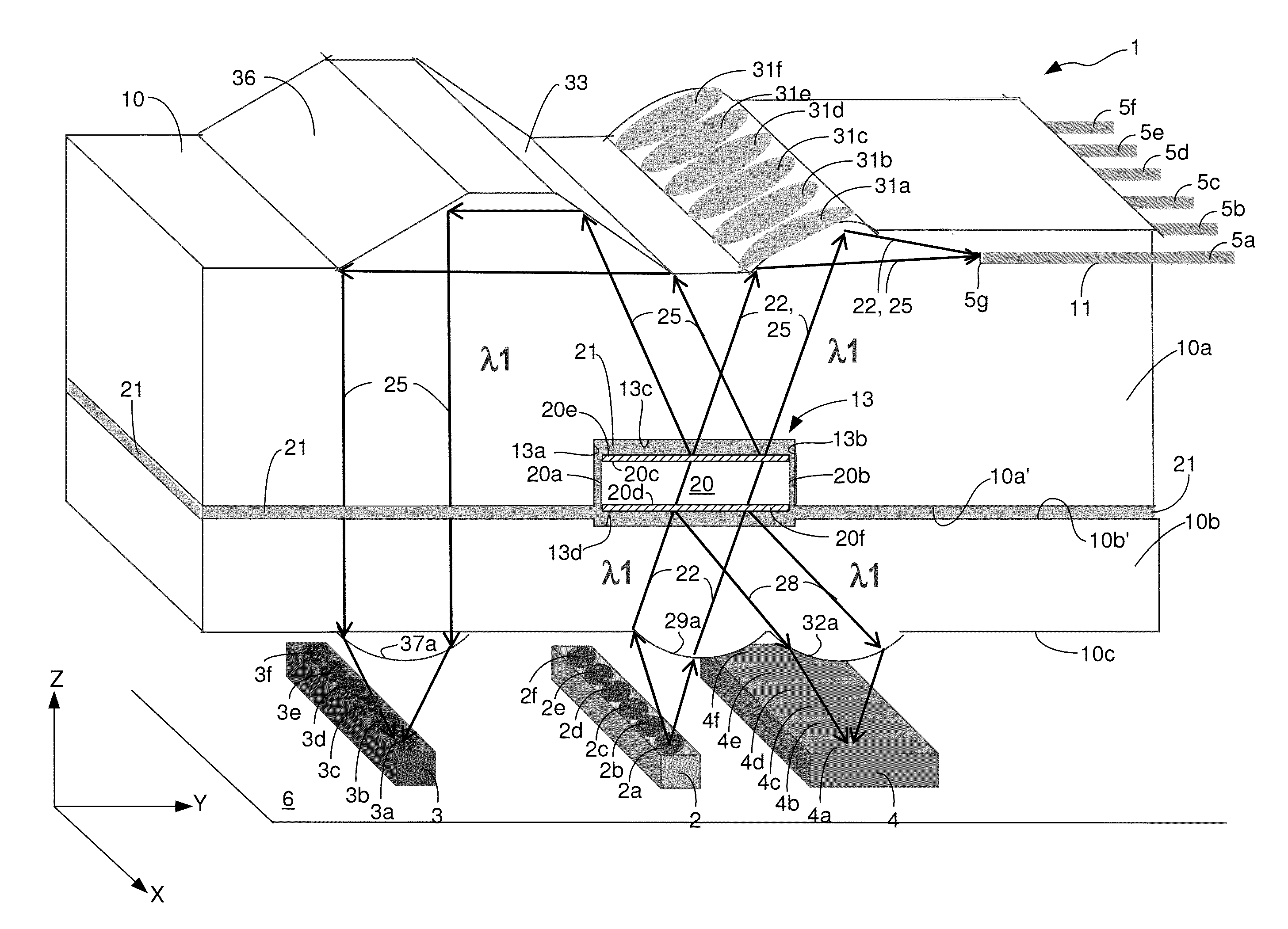
The patent describes a new type of optical transceiver module that can send and receive optical signals simultaneously over a single fiber cable. This allows for more efficient and bidirectional communication between devices over optical networks. The technical effect is improved data transmission speed and reliability over optical links.

Problems solved by technology

While various transceiver and optical fiber link designs enable the overall bandwidth, or data rate, of optical fiber links to be increased, there are limitations on the extent to which currently available technologies can be used to improve the bandwidth of an optical fiber link.
However, in order to achieve such a link, multiple sets of parallel optics and a corresponding number of optical fibers are needed, which significantly adds to the costs associated with such links.
Therefore, there is difficulty associated with scaling such links to achieve increasingly higher bandwidths.
However, bidirectional optical links also present challenges in terms of dealing with optical crosstalk, return loss and signal-to-noise ratio (SNR).

Method used


Image

  • Bidirectional parallel optical transceiver module and a method for bidirectionally communicating optical signals over an optical link
  • Bidirectional parallel optical transceiver module and a method for bidirectionally communicating optical signals over an optical link
  • Bidirectional parallel optical transceiver module and a method for bidirectionally communicating optical signals over an optical link

Examples


Embodiment Construction

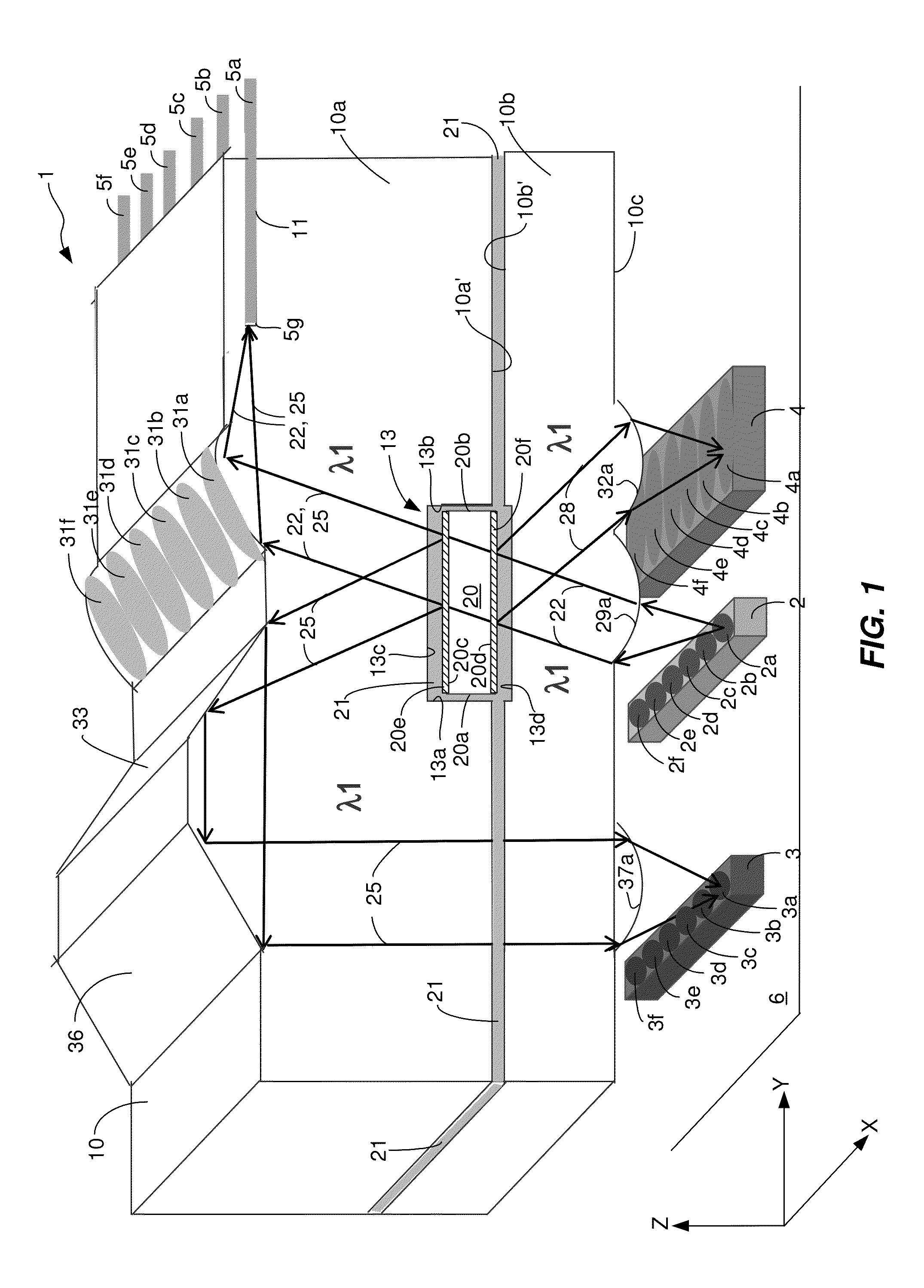
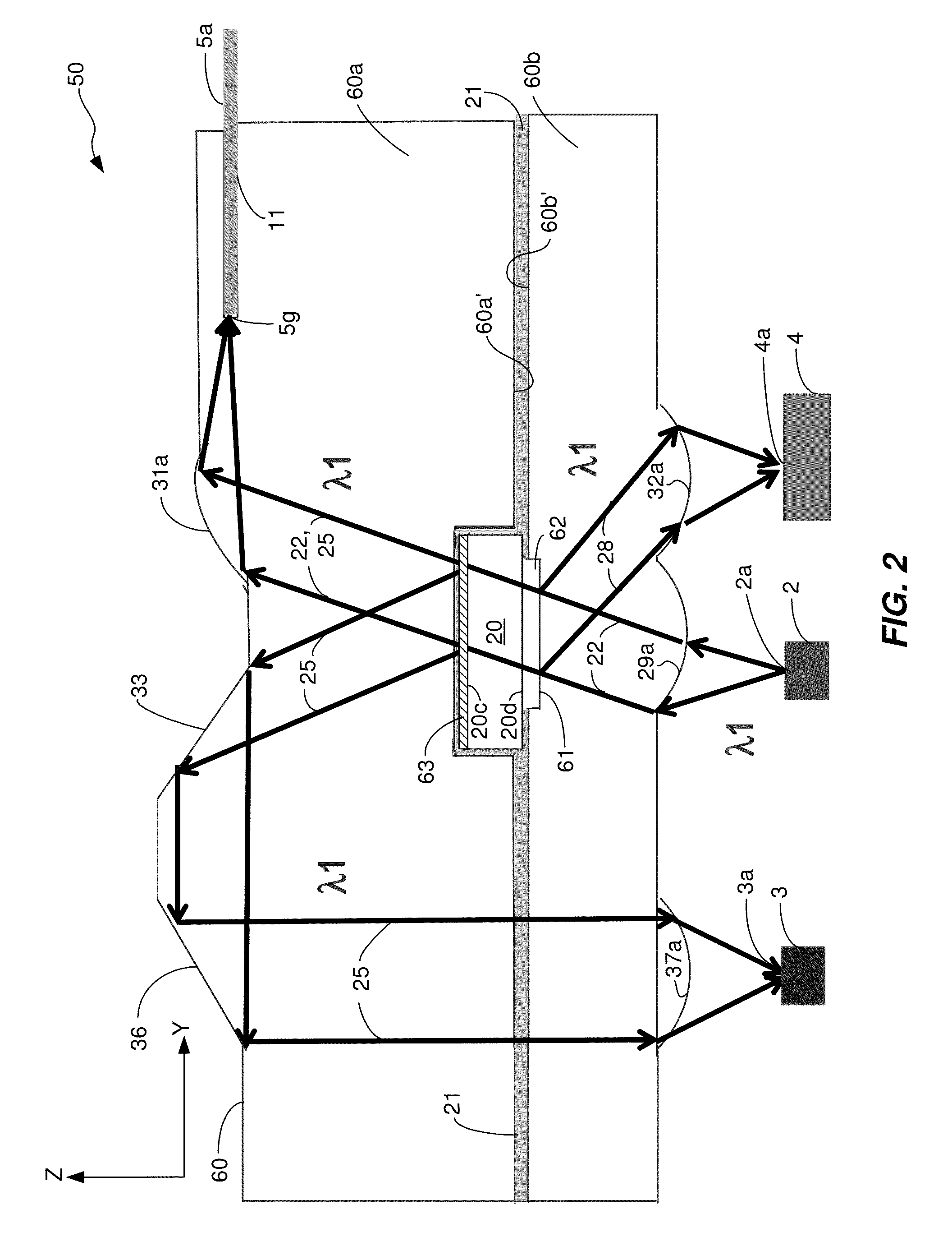
[0023]The invention is directed to bidirectional parallel optical transceiver modules and methods for communicating bidirectionally over optical links. The bidirectional parallel optical transceiver modules have features that ensure relatively low optical crosstalk, relatively low return loss and relatively high SNR. In addition, the modules have an in-line, zig-zag configuration that allows the modules to be compact and to have high bidirectional channel density for achieving high bandwidth.

[0024]In accordance with some illustrative embodiments, features of the modules accommodate existing form factors for existing vertical cavity surface emitting laser diode (VCSEL) arrays and p-doped-instrinsic-n-doped (P-I-N) diode arrays, which facilitates designing and assembling the modules. In accordance with some illustrative embodiments, a single wavelength is used for transmitting and receiving optical signals over a bidirectional optical link. In accordance with other illustrative embodi...


PUM


Abstract

Bidirectional parallel optical transceiver modules for use in optical links and methods for communicating bidirectionally over the links are provided. The bidirectional parallel optical transceiver modules have features that ensure relatively low optical crosstalk, relatively low return loss and relatively high SNR. In addition, the modules have an in-line, zig-zag configuration that allows the modules to be compact and to have high bidirectional channel density for achieving high bandwidth.

Description

TECHNICAL FIELD OF THE INVENTION[0001]The invention relates to optical communications networks over which data is communicated in the form of optical signals transmitted and received over optical waveguides. More particularly, the invention relates to bidirectional optical links, bidirectional parallel optical transceiver modules for use in the links, and methods for bidirectionally communicating optical signals over the links.BACKGROUND OF THE INVENTION[0002]In optical communications networks, optical transceivers are used to transmit and receive optical signals over optical fibers. An optical transceiver generates amplitude and / or phase and / or polarization modulated optical signals that represent data, which are then transmitted over an optical fiber coupled to the transceiver. Each transceiver includes a transmitter side and a receiver side. On the transmitter side, a laser light source generates laser light and an optical coupling system receives the laser light and optically co...

Claims


Application Information

Patent Timeline
IPC IPC(8): H04B10/40
CPCH04B10/40G02B6/4246G02B6/4214
Inventor SHAO, BINGCHEN, YE
Owner AVAGO TECH INT SALES PTE LTD
Learn More