
Efficient Method Based on the Electromagnetic Time Reversal to Locate Faults in Power Network

a technology of electromagnetic time reversal and fault location, applied in the field of power system operation, can solve the problems of large bandwidth measuring system, affecting the accuracy of these procedures,

Active Publication Date: 2014-10-09
ECOLE POLYTECHNIQUE FEDERALE DE LAUSANNE (EPFL)
View PDF1 Cites 54 Cited by
  • Summary
  • Abstract
  • Description
  • Claims
  • Application Information

AI Technical Summary

Benefits of technology

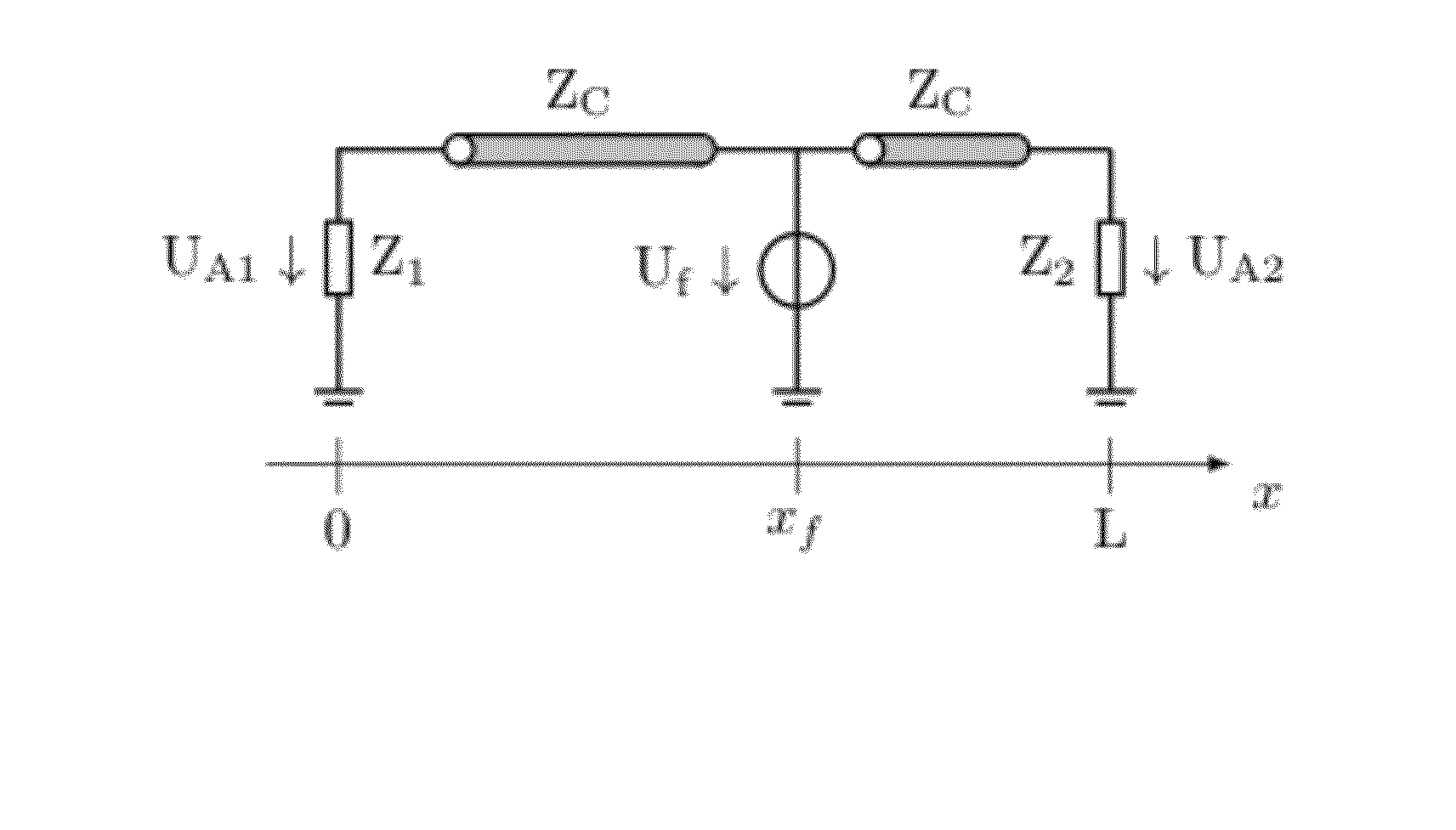
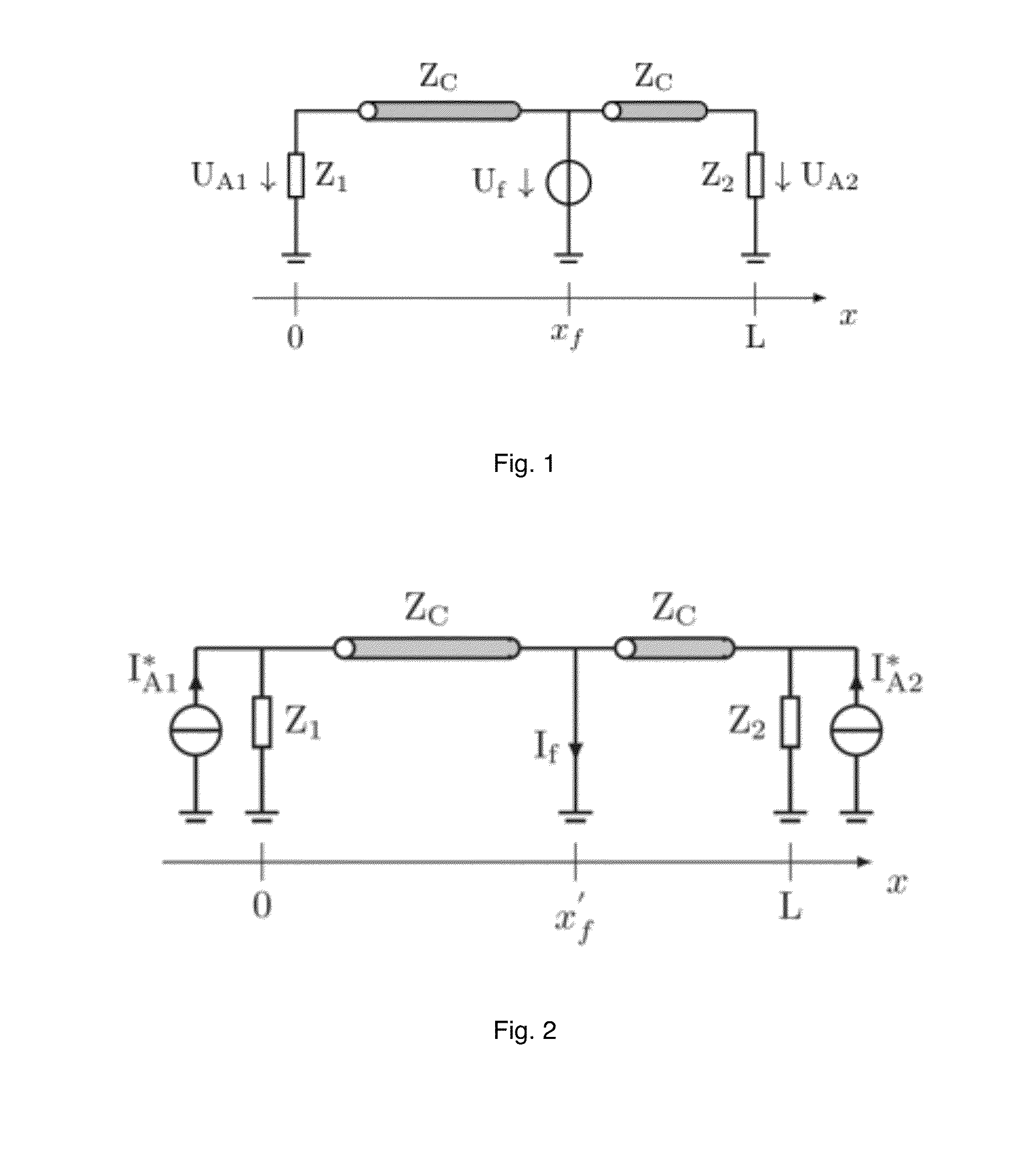
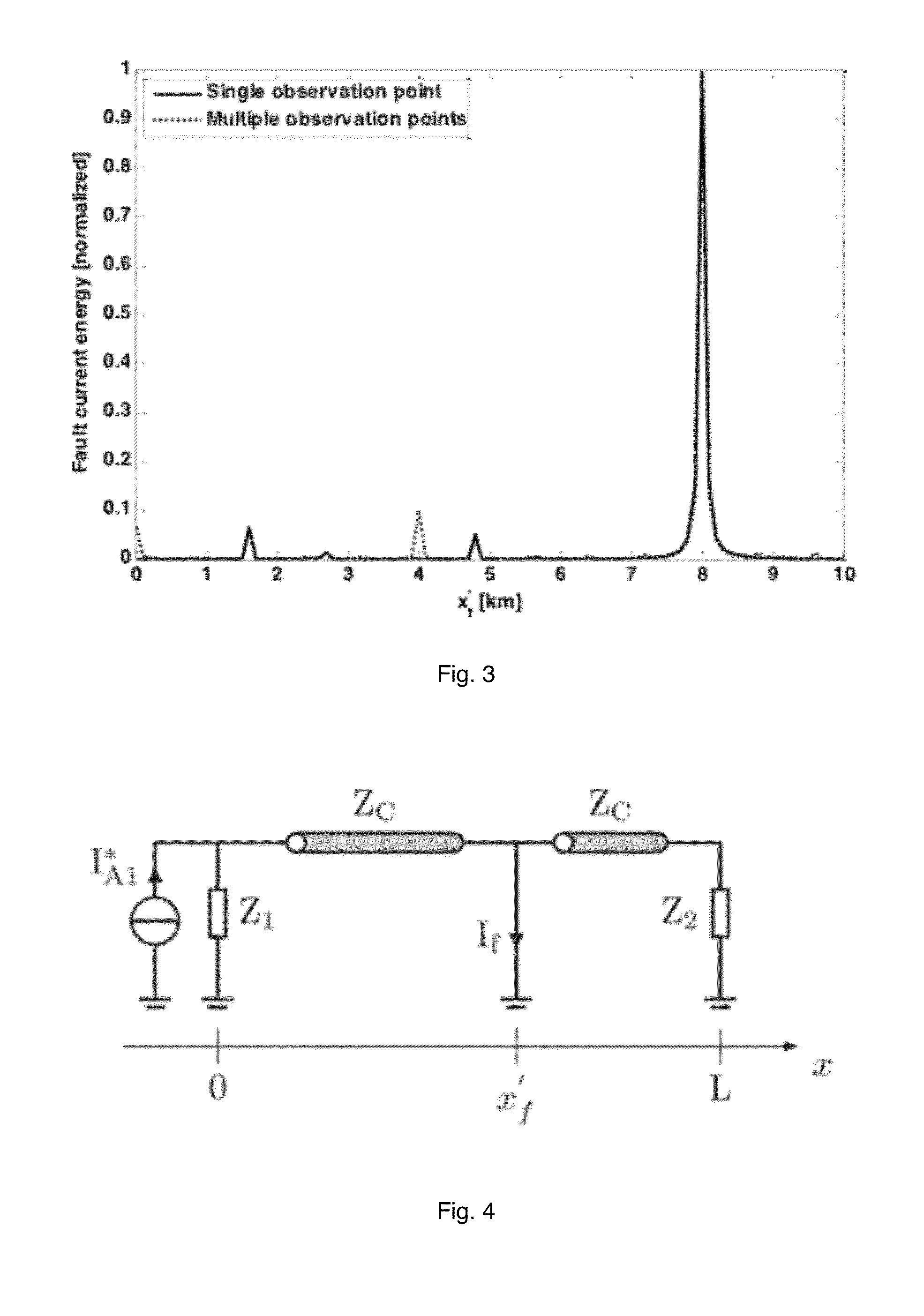
The invention is a method for determining the location of a fault in a power network with multiple conductors. It involves measuring the electromagnetic signals caused by the fault at different points along the conductor lines, and creating a model of the network based on its topology and electrical parameters. The method then reverses the time of the measured signals and back-injects them into the network model to create an energy map of the fault current. By calculating the energy of the fault current at different locations in the model, the method can identify the location of the fault. The measurement can be a current or voltage measurement. Overall, the method improves the accuracy and reliability of fault detection in power networks.

Problems solved by technology

However, the presence of other sources (e.g. associated with the increasing penetration of dispersed generation) can largely affect the accuracy of these procedures.
The major drawbacks of this second category of methods are: (i) they require an assessment between the number of observation points vs the number of possible multiple fault location solutions; (ii) they require large bandwidth measuring systems.

Method used


Image

  • Efficient Method Based on the Electromagnetic Time Reversal to Locate Faults in Power Network
  • Efficient Method Based on the Electromagnetic Time Reversal to Locate Faults in Power Network
  • Efficient Method Based on the Electromagnetic Time Reversal to Locate Faults in Power Network

Examples


application examples

[0097]Inhomogeneous Network Composed of Mixed Overhead-Coaxial Cable Lines.

[0098]In this section, we present a first numerical validation of the proposed technique. For this purpose, reference is made to the case of a network composed of a three-conductor transmission line and an underground coaxial cable (see FIG. 11).

[0099]The overhead line length is 9 km and the cable length is 2 km. They are modeled by means of a constant-parameter model implemented within the EMTP-RV simulation environment [30]-[32]. Both the overhead line and the cable parameters have been inferred from typical geometries of 230 kV lines and cables. The series impedance and shunt admittance matrices for the line and cable are given by (22)-(25) and have been calculated in correspondence of the line and cable switching frequency.

ZLine=[1.10+j15.321.00+j5.801.00+j4.641.00+j5.801.09+j15.331.00+j5.801.00+j4.641.00+j5.801.00+j15.32]Ωkm(22)Yline=[2·10-4+j67.53-j16.04-j7.91-j16.042·10-4+j70.12-j16.04-j7.91-j16.042·10...


PUM


Abstract

A time reversal process for determining a fault location in an electrical power network comprising multi-conductor lines, comprises measuring at an observation point located anywhere along one of the multi-conductor lines, for each of the conductors of the multi-conductor line, respectively a fault-originated electromagnetic transient signal; defining a set of guessed fault locations each having a different determined location in the electrical power network, and each of the guessed fault locations is attributed a same arbitrary fault impedance; defining a network model for the electrical power network, based on its topology and multi-conductor lines electrical parameters capable of reproducing in the network model the electromagnetic traveling waves; and computing for each conductor a time inversion of the measured fault-originated electromagnetic transients signal. The time reversal process method further comprises, as detailed herein, back-injecting a computed time inversion; calculating fault current signal energy; and identifying the fault location.

Description

TECHNICAL FIELD[0001]The present invention is in the field of power systems operation and more precisely relates to a fault location functionality of power systems.INTRODUCTION[0002]The fault location functionality is an important on-line process required by power systems operation. It has a large influence on the security and quality of supply.[0003]In transmission networks, this functionality is needed for the identification of the faulted line and the adequate reconfiguration of the network to anticipate severe cascading consequences. In distribution networks, fault location is more associated to the quality of service in terms of duration of interruptions when permanent faults occur. Still with reference to distribution networks, the increasing use of distributed generation calls for accurate and fast fault location procedures aimed at minimizing the network service restoration time, and, consequently, minimizing the unsupplied power.[0004]As summarized in [1], [2], various proc...

Claims


Application Information

Patent Timeline
IPC IPC(8): G01R31/08
CPCG01R31/08G01R31/086Y04S10/52G01R31/085
Inventor PAOLONE, MARIORACHIDI-HAERI, FARHADMAHMOUDIMANESH, HOSSEINRAZZAGHI, REZALUGRIN, GASPARD
Owner ECOLE POLYTECHNIQUE FEDERALE DE LAUSANNE (EPFL)
Learn More