Comfort headrest

Inactive Publication Date: 2014-10-09
AISIN TECHN CENT OF AMERICA
View PDF6 Cites 10 Cited by
  • Summary
  • Abstract
  • Description
  • Claims
  • Application Information

AI Technical Summary

Benefits of technology

The patent text describes a headrest that is designed to provide passengers with a comfortable pillow-like cushion. This headrest can be adjusted to a preferred angle to provide extra comfort for passengers during long drives. The technical effect of this invention is to improve the comfort of passengers in vehicles.

Problems solved by technology

However, U.S. Pat. No. 7,717,517 B2 has a drawback in that the side wings do not go all the way back, which does not give the appearance of a normal headrest when the side wings are not in use.
However, both U.S. Pat. No. 7,144,083 B2 and U.S. Pat. No. 7,131,698 B2 have a drawback in that the amount of area on the center portion where the head normally rests is greatly reduced when side members are rotated towards the user's head.
Furthermore, creases in the headrest exist when the side members are flat and not rotated, which can cause discomfort to the user.

Method used


Image

  • Comfort headrest
  • Comfort headrest
  • Comfort headrest

Examples


first embodiment

[0026]FIG. 1 displays an isometric view of the assembled headrest 100 which includes a side wing 1. The headrest 100 includes a form which is transparent in this Figure. The structure within the headrest 100 will be described with respect to FIG. 2.

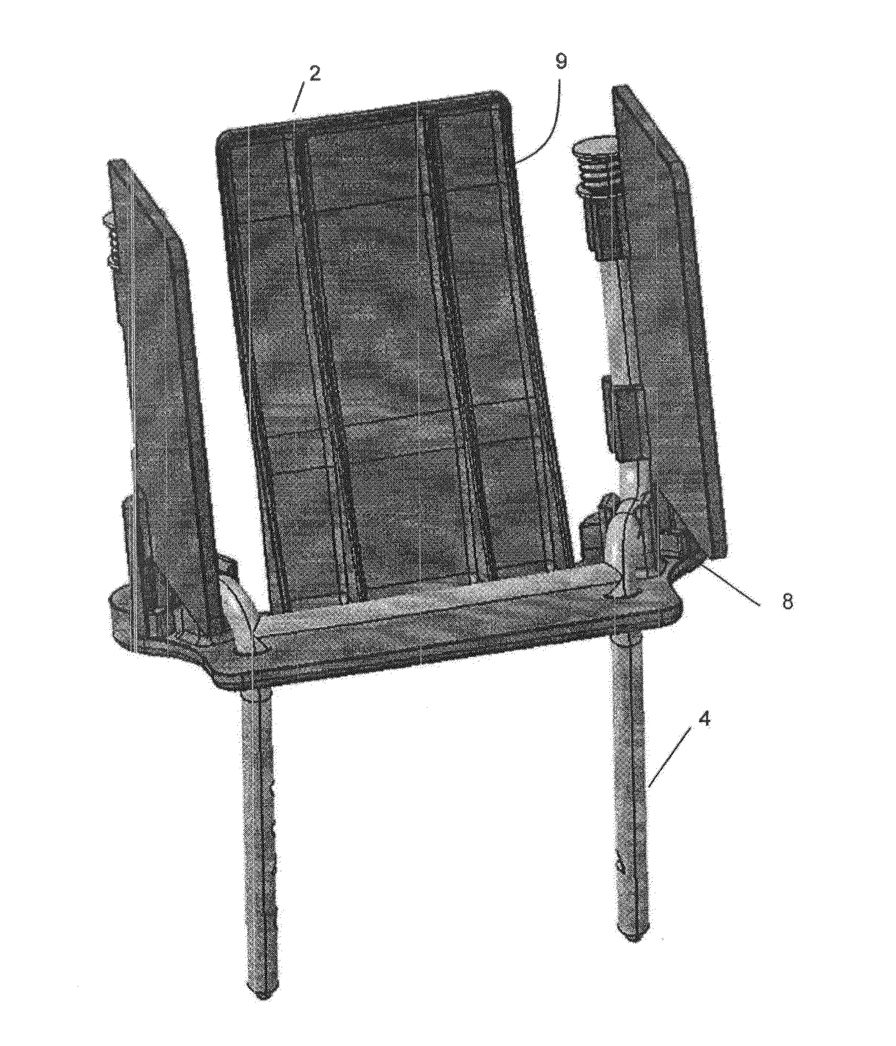
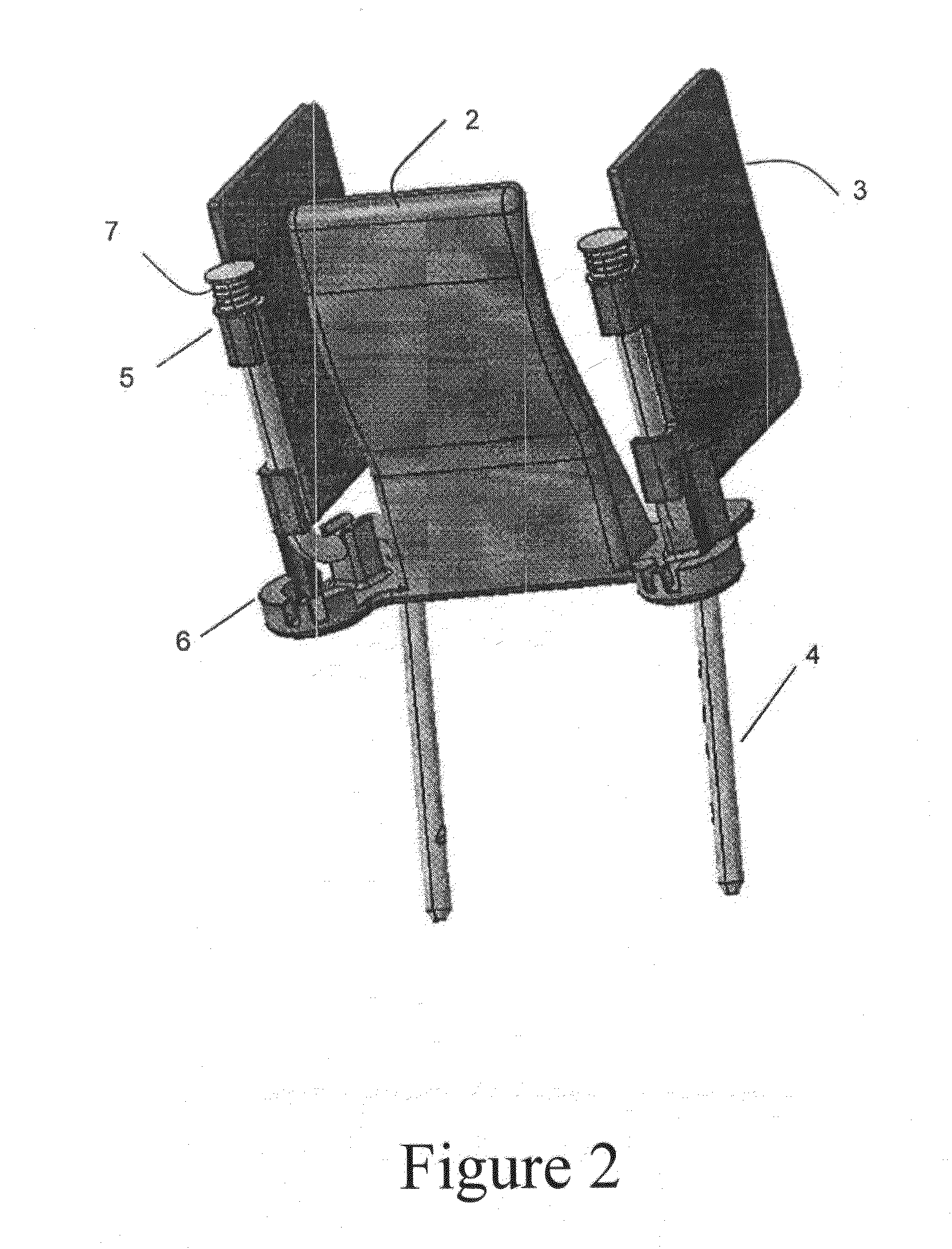
[0027]FIG. 2 shows the interior structure of the headrest 100 and displays all of the functional parts. The interior structure of the headrest 100 includes a resin plate 2 for head impact, left and right side wing structures 3, a headrest post 4, attachment method 5 to attach the side wing structure to the headrest post 4, a locking mechanism 6, and two compression springs 7.

[0028]The resin plate 2 is a resilient structure provides the primary head support of the headrest 100 Shown in FIG. 2 and FIG. 3, the resin plate 2 has a generally rectangular shape when viewed from a front direction. The resin plate 2 extends from a base 8 in a vertical direction as shown in FIG. 2. When viewed in profile, the resin plate 2 includes a deformation or...

second embodiment

[0040]A second embodiment is illustrated in FIGS. 9-13. The second embodiment includes a headrest 200. FIG. 9 illustrates a front view of the assembled headrest 200 which includes two side wings 21 that are flush with a front face when in the closed position.

[0041]FIG. 10 illustrates a side view of the headrest 200 which includes a side wall 30 to hide inner locking and rotating mechanisms that function the side wings 21. Also shown is a button 31 that is used to slide and rotate the side wing 21 out.

[0042]Similar to the first embodiment, the side wings 21 include side wing structures which rotate about axes of headrest posts 24. The side wings 21 are held in place by slide rail or rails that that extend and rotate the side wings 21. Specifically, side wings 21 slide forward after being released by the button 31 along the rails. Once the side wing 21 has cleared the front face of the headrest 200, side wings 21 are rotatable around the axes of the posts 24 to predetermined positions...


PUM


Abstract

A vehicle headrest, including two side wings at opposite ends of the headrest that rotate around respective axes; and a locking mechanism that locks each of the side wings, and backwards movement is restricted by the locking mechanism when each side member is rotated around the respective axis.

Description

BACKGROUND OF THE INVENTION[0001]1. Field of the Invention[0002]Exemplary aspects of the present invention relate to a headrest of a vehicle to increase the comfort of a user during prolonged use.[0003]2. Description of the Related Art[0004]Seats of a vehicle such as an automobile are provided with a headrest for the safety and comfort of an occupant (user). The headrest provides protection to the occupant in the event of a crash by helping to prevent head, neck, or spinal injuries by limiting the rearward movement of the occupant's head. A headrest also provides comfort to a user by providing a place to rest one's head especially for a long drive.[0005]Headrests may be provided in special arrangements to enhance the comfort of the user. For example, certain materials such as foam may be used to provide a soft cushion. Also, the shape of the headrest may be designed to enhance comfort. For example, U.S. Pat. No. 7,717,517 B2 describes a headrest that has side wings that pivot around...

Claims


Application Information

Patent Timeline
IPC IPC(8): B60N2/48
CPCB60N2/4882B60N2/885
Inventor SZCZYGIEL, LINDSEYHOWLETT, MIKEARCHAMBEAU, ERICTAKEUCHI, KATSUHIKO
Owner AISIN TECHN CENT OF AMERICA
Why Eureka
Try Eureka