
Quick disconnect for a drive unit

a technology of drive unit and disconnection device, which is applied in the direction of friction clutches, interlocking clutches, clutches, etc., can solve the problems of affecting the reliability of the drive uni

Inactive Publication Date: 2014-10-09
AUBURN GEAR
View PDF5 Cites 0 Cited by
  • Summary
  • Abstract
  • Description
  • Claims
  • Application Information

AI Technical Summary

Benefits of technology

The mechanism ensures reliable disengagement of the wheel drive from the vehicle power source, even when under pressure, with clear visual indications of its configuration, allowing operation without special tools and in adverse conditions.

Problems solved by technology

These known disconnect mechanisms purport to provide convenience to the user, but do so at a cost in terms of flexibility and robustness.
For example, industrial machinery utilizing drive units may be subjected to frequent engagement and disengagement in harsh and unpredictable service environments, such as in off-road in varied terrain, in heavy-duty applications, and / or in inclement weather conditions.
However, this resistance places the transmission components under pressure, including the components of a quick-disconnect mechanism.
Spring pressure may be insufficient to overcome the substantial frictional forces that arise between components of a wheel drive when under pressure, effectively rendering a mechanism that relies on such disengagement mechanisms unable to effect the desired disconnection of the wheel drive.
Similarly, disengaging a disconnect mechanism by a user-exerted pull-out force may also be difficult or impossible when the mechanism is under pressure, particularly where the user himself may be subject to adverse conditions (i.e., rain, mud, cold, etc).

Method used


Image

  • Quick disconnect for a drive unit
  • Quick disconnect for a drive unit
  • Quick disconnect for a drive unit

Examples


Embodiment Construction

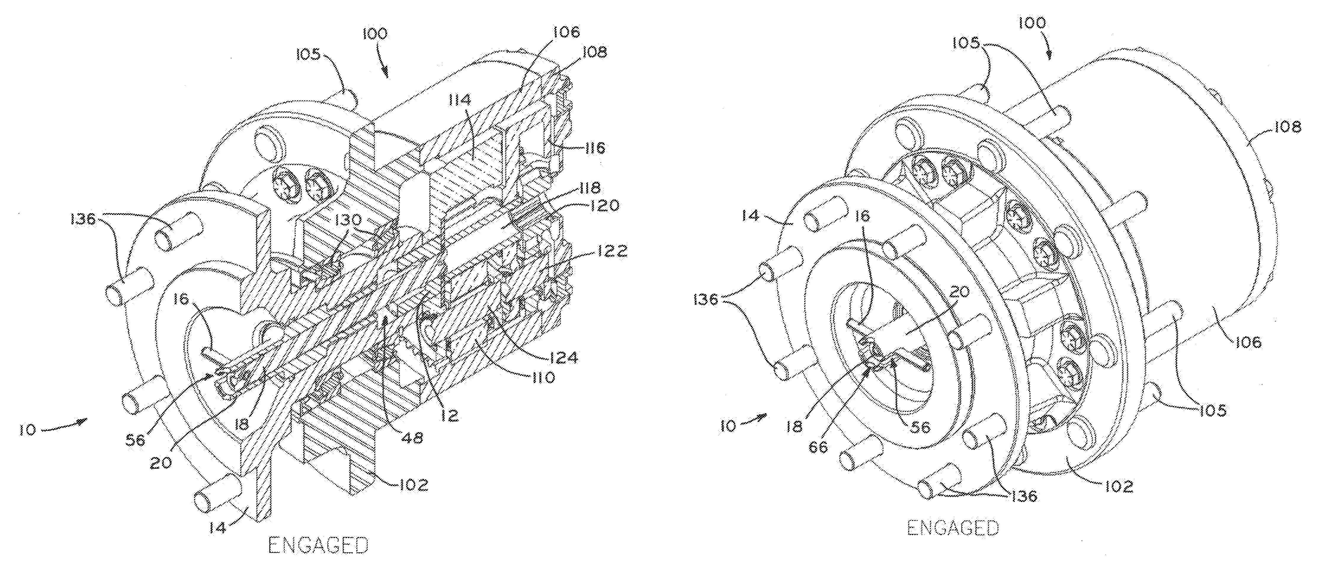
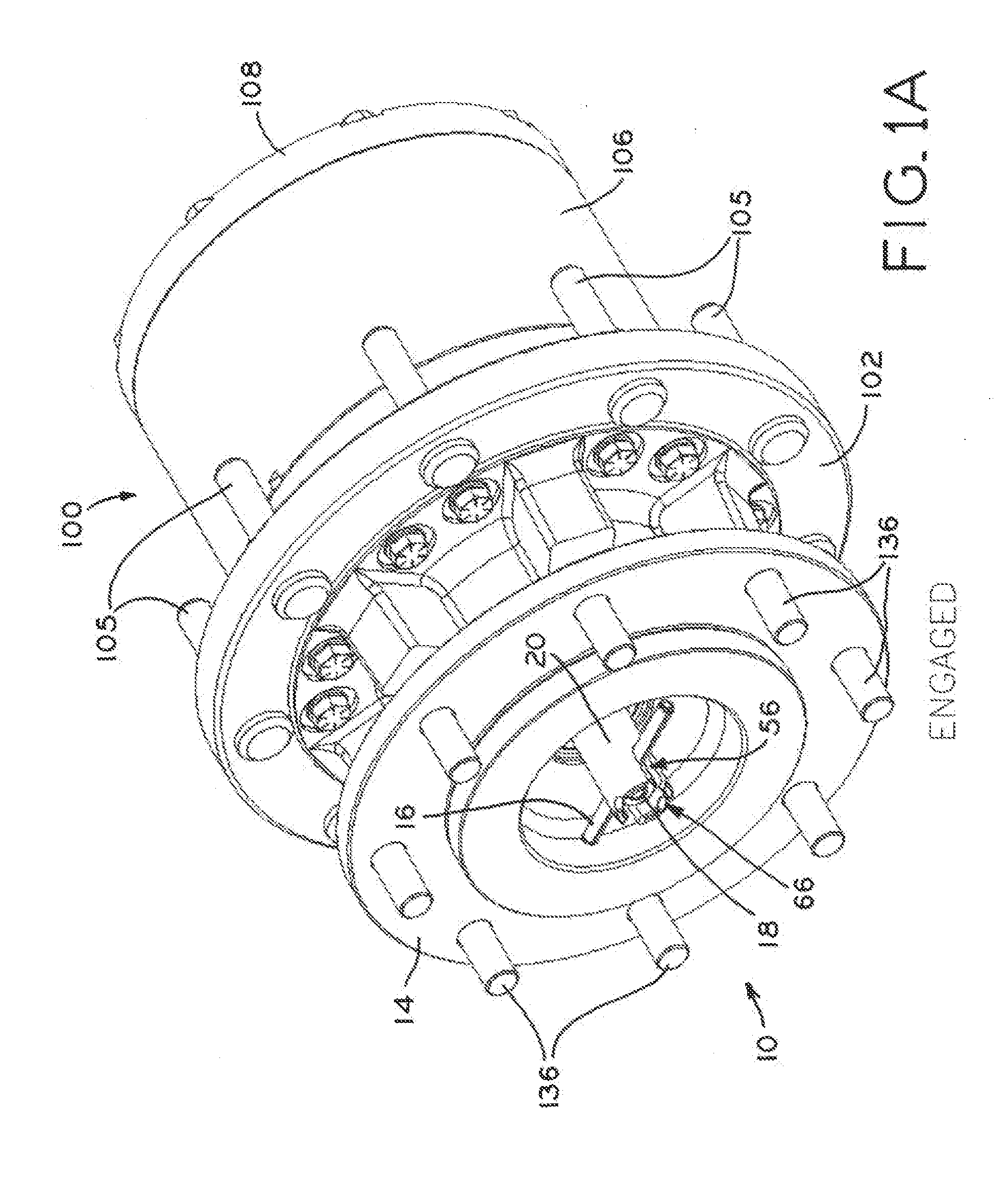
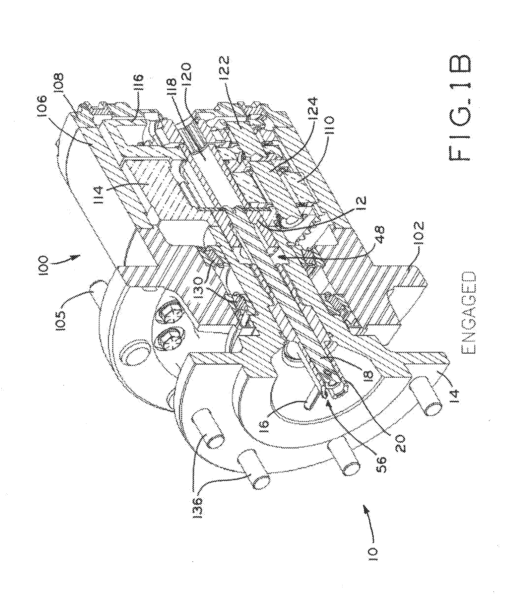
[0037]The present disclosure provides a drive unit disconnect mechanism 10 configurable between an engaged position (FIGS. 1A-1C), a “handle-disengaged” position (FIG. 2A-2C), and a “screw-disengaged” position (FIGS. 3A-3C). In the engaged configuration, coupling gear 12 of mechanism 10 rotationally fixes output hub 14 to planetary gear transmission assembly 101 of drive unit 100 (FIGS. 1B and 1C, described in detail below).

[0038]In the handle-disengaged position, handle 16 is used to draw inner disconnect shaft 18 out of outer disconnect shaft 20, so that coupling gear 12 is drawn into output hub 14 and fully disengages from planetary transmission assembly 101 of drive unit 100 (FIGS. 2B and 2C). As best shown in FIG. 2A, visual indication of the handle-disengaged configuration is provided by inner disconnect shaft 18 protruding from outer disconnect shaft 20 and handle 16 being out of alignment with slots 56 formed in outer shaft 20.

[0039]In the screw-disengaged configuration, out...


PUM


Abstract

A drive unit disconnect mechanism is operable to transmit or disconnect power from a vehicle power source to a driven unit, and can be disengaged by multiple methods depending on how much force is required to separate the internal components of the mechanism. In a first, relatively quicker method, a handle is pulled axially away from the hub to withdraw and internal gear from splined engagement with a corresponding driven gear. In a second, relatively slower method, the handle is rotated to threadably withdraw the entire disconnect mechanism from the hub, which in turn withdraws the internal gear from splined engagement with the driven gear. The quicker method is desirable in most instances, but the slower method allows disconnection of the driven unit from the vehicle power source when gear pressure prevents or impedes the quicker method.

Description

CROSS-REFERENCE TO RELATED APPLICATIONS[0001]This application claims the benefit under 35 U.S.C. §119(e) of United States Provisional Patent Application Ser. No. 61 / 370,474 filed Aug. 4, 2010 and entitled QUICK DISCONNECT FOR A DRIVE UNIT, the entire disclosure of which is hereby expressly incorporated herein by reference.BACKGROUND[0002]1. Technical Field[0003]The present disclosure relates to vehicle power transmission units, and, more particularly, to disconnect devices for selectively disengaging the vehicle transmission unit from driven vehicle wheels.[0004]2. Description of the Related Art[0005]Large industrial machinery, such as earth moving equipment and other construction vehicles, may use individual power transmission units mounted at the hub of each driven wheel to accomplish sufficient gear reduction for the heavy loads, large wheels, and low speeds frequently employed by such vehicles. These individual power transmission units are sometimes referred to as “wheel drives”...

Claims


Application Information

Patent Timeline
Patent Type & Authority Applications(United States)
IPC IPC(8): F16D11/14
CPCF16D2011/004F16D11/14Y10T74/19642
Inventor FORREST, JAMES L.
Owner AUBURN GEAR
Learn More