
Electrophotographic process cartridge and electrophotographic apparatus

a technology of electrophotographic image and process cartridge, which is applied in the direction of electrographic process, instrument, corona discharge, etc., can solve the problems of horizontal streaks produced in electrophotographic images, and achieve the effect of high-quality electrophotographic and improved uneven charging

Active Publication Date: 2014-10-02
CANON KK
View PDF3 Cites 13 Cited by
  • Summary
  • Abstract
  • Description
  • Claims
  • Application Information

AI Technical Summary

Benefits of technology

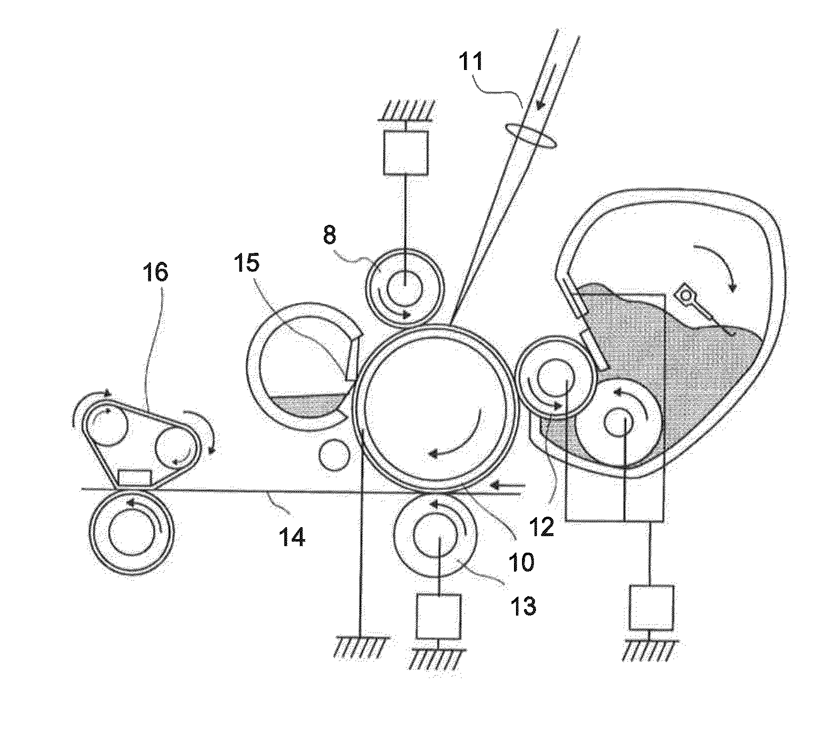
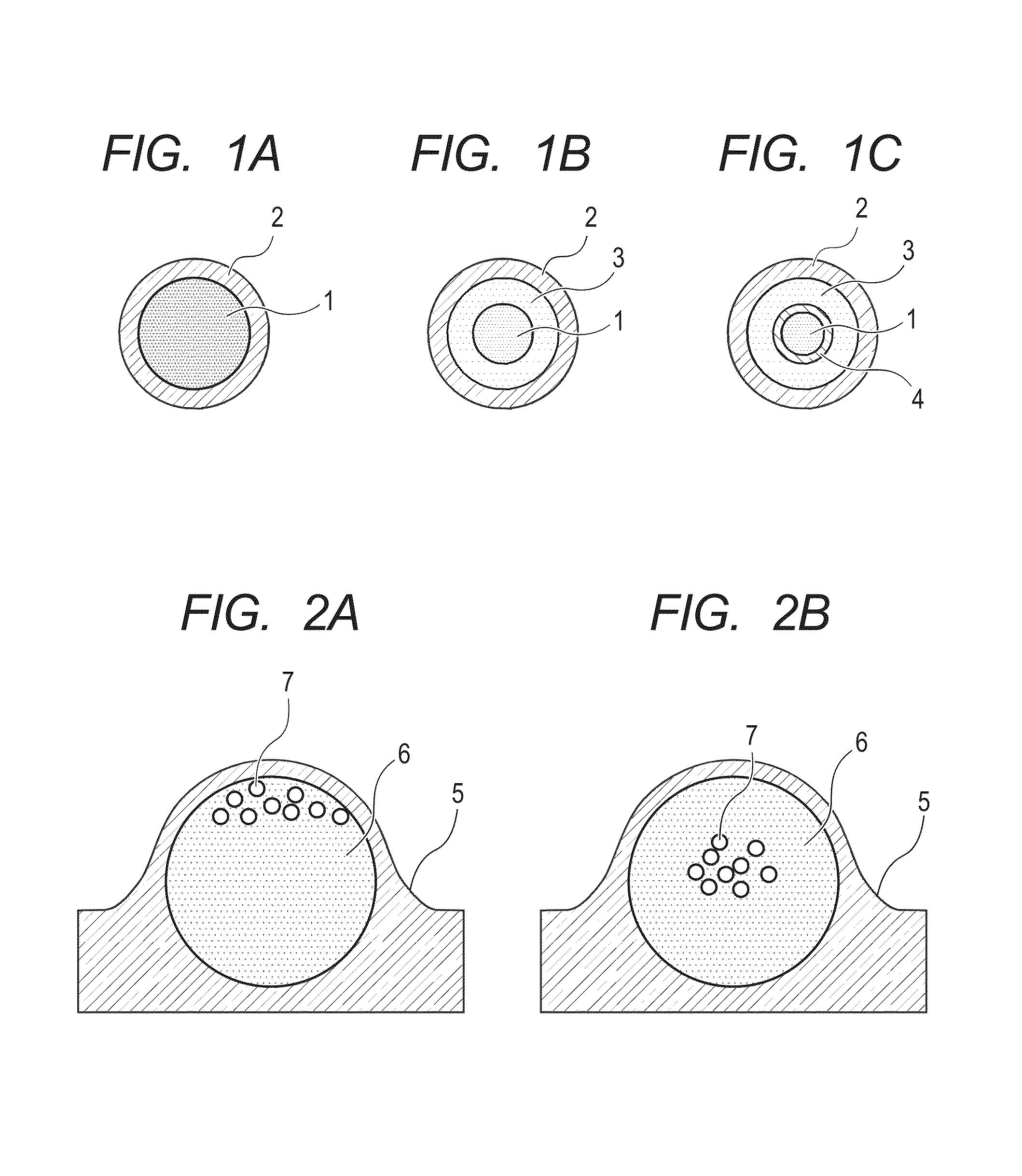
The present invention provides an electrophotographic process cartridge that improves uneven charging and suppresses production of a banding image. This is achieved by using a charging member with a roughened surface, which prevents uneven charging and a slip between the charging member and the electrophotographic photosensitive member. This technology effectively suppresses the production of a banding image even when the charging member is charged in contact with an electrophotographic photosensitive member having enhanced lubrication of the surface. Ultimately, this invention allows for the formation of high-quality electrophotographic images.

Problems solved by technology

Such a slip causes uneven charging of the electrophotographic photosensitive member, leading to horizontal streaks produced in an electrophotographic image.

Method used


Image

  • Electrophotographic process cartridge and electrophotographic apparatus
  • Electrophotographic process cartridge and electrophotographic apparatus
  • Electrophotographic process cartridge and electrophotographic apparatus

Examples


examples

[0247]Hereinafter, the present invention will be described more in details by way of specific Examples. First, prior to Examples, Production Examples A1 to A12 of the electrophotographic photosensitive member, the method of evaluating the resin particle, Production Examples B1 to B20 of the resin particle, Production Examples C1 and C2 of the fine particle, and Production Examples D1 to D20 of the charging member will be described. In the description below, “parts” mean “parts by mass”.

a. Production Examples of Electrophotographic Photosensitive Member

production example a1

[0248]An aluminum cylinder having a diameter of 24 mm and a length of 261.6 mm was used as the support. Next, a mixed solvent of 10 parts of SnO2 coated barium sulfate (conductive particle), 2 parts of titanium oxide (pigment for adjusting resistance), 6 parts of a phenol resin (binder resin), 0.001 parts of a silicone oil (leveling agent), 4 parts of methanol, and 16 parts of methoxypropanol was used to prepare a coating solution for an electrically conductive layer. The coating solution for an electrically conductive layer was applied onto the support by immersion coating, and cured (thermally cured) for 30 minutes at 140° C. to form an electrically conductive layer having a layer thickness of 15 μm on the support.

[0249]Next, 3 parts of N-methoxymethylated nylon and 3 parts of copolymerized nylon were dissolved in a mixed solvent of 65 parts of methanol and 30 parts of n-butanol to prepare a coating solution for an intermediate layer. The coating solution for an intermediate layer...

production examples a2

to A6

[0253]Electrophotographic photosensitive members A2 to A6 were produced in the same manner as in Production Example A1 except that the kind and content of the compound (3) in Production Example A1 were changed as shown in Table 4.

Production Example A7

[0254]In formation of the charge-transport layer in Production Example A1, the drying temperature was changed to 145° C. and the drying time was changed to 60 minutes. The mixing ratio of the solvent was changed as shown in Table 4. Except these, an electrophotographic photosensitive member A7 was produced in the same manner as in Production Example A1.

Production Examples A8 and A9

[0255]Electrophotographic photosensitive members A8 and A9 were produced in the same manner as in Production Example A1 except that the layer thickness of the charge-transport layer in Production Example A1 was changed to 30 μm in Production Example A8 and to 10 μm in Production Example A9.


PUM


Abstract

Uneven charging is improved, and production of a banding image attributed to a slip between the charging member and the electrophotographic photosensitive member is suppressed. An electrophotographic process cartridge including a charging member and an electrophotographic photosensitive member which is electrically charged upon being brought into contact with the charging member, wherein the charging member includes a electro-conductive substrate and a surface layer formed on the electro-conductive substrate; the surface layer contains at least a binder resin, an electron conductive agent, and a resin particle having a plurality of pores inside thereof; the surface of the surface layer has a protrusion derived from the resin particle; the electrophotographic photosensitive member includes a support and a photosensitive layer formed on the support; and the surface layer of the electrophotographic photosensitive member contains a specific component.

Description

CROSS-REFERENCE TO RELATED APPLICATIONS[0001]This application is a continuation of International Application No. PCT / JP2013 / 005766, filed Sep. 27, 2013, which claims the benefit of Japanese Patent Application No. 2013-014877, filed Jan. 29, 2013.BACKGROUND OF THE INVENTION[0002]1. Field of the Invention[0003]The present invention relates to an electrophotographic process cartridge and an electrophotographic image forming apparatus (hereinafter referred to as an “electrophotographic apparatus”).[0004]2. Description of the Related Art[0005]A method for charging the surface of an electrophotographic photosensitive member includes a contact charging method using a charging member in contact with the surface of the electrophotographic photosensitive member. It is said that the contact charging method easily produces uneven charging of the surface of the electrophotographic photosensitive member due to a narrow discharge region between the charging member and the electrophotographic photo...

Claims


Application Information

Patent Timeline
Patent Type & Authority Applications(United States)
IPC IPC(8): G03G15/00G03G21/18G03G15/02B05C1/08
CPCG03G21/18G03G15/02G03G15/0233G03G5/147G03G5/05G03G15/75G03G5/14708G03G5/1476G03G5/14773G03G5/14752G03G5/14756G03G5/056G03G5/0564G03G5/0589G03G5/14786G03G21/1814
Inventor MIYAGAWA, NOBORUKOIDE, SATOSHIAOYAMA, TAKEHIKOTANAKA, DAISUKE
Owner CANON KK
Learn More