
Image forming apparatus

a technology of image forming apparatus and charging roller, which is applied in the direction of electrographic process apparatus, instruments, corona discharge, etc., can solve the problems of poor image quality, hinder the charging roller from uniformly charging the surface of the photosensitive drum, and toner contamination of the charging roller, etc., to reduce the adverse

Inactive Publication Date: 2010-03-04
CANON KK
View PDF8 Cites 2 Cited by
  • Summary
  • Abstract
  • Description
  • Claims
  • Application Information

AI Technical Summary

Benefits of technology

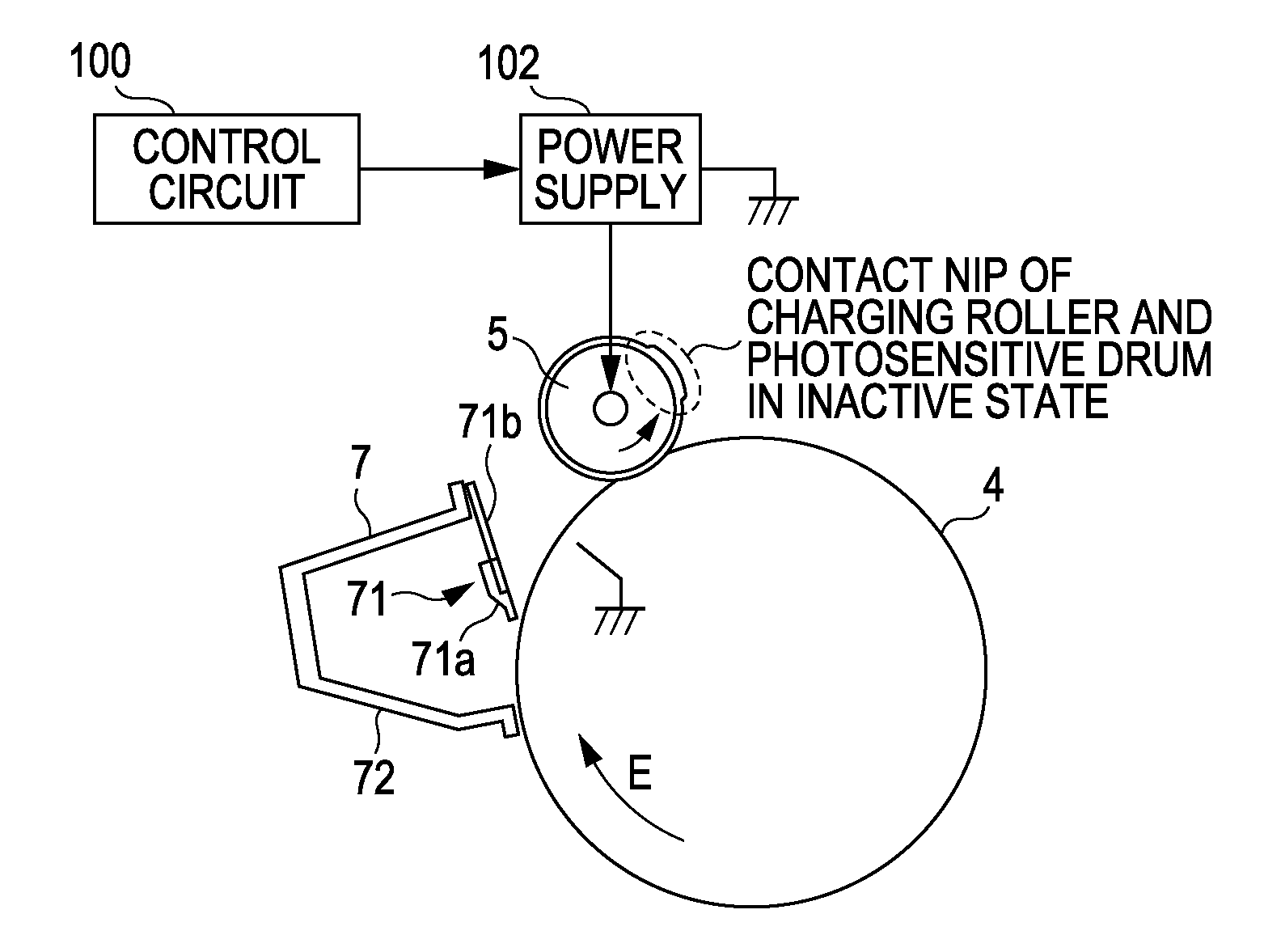
[0010]The present invention provides an image forming apparatus capable of reducing an adverse effect shown in an image in a cycle of a charging roller resulting from contamination of the charging roller with toner.
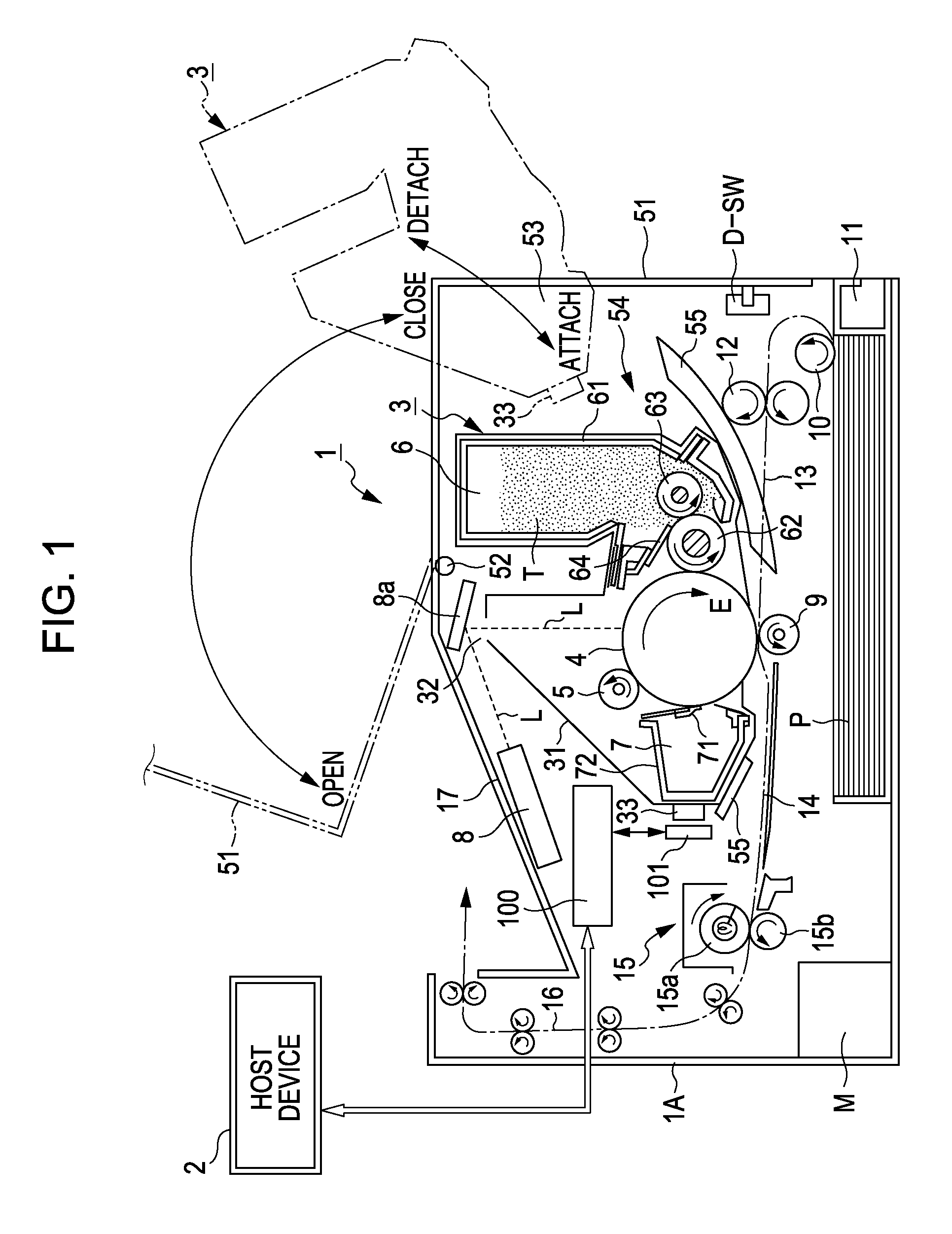
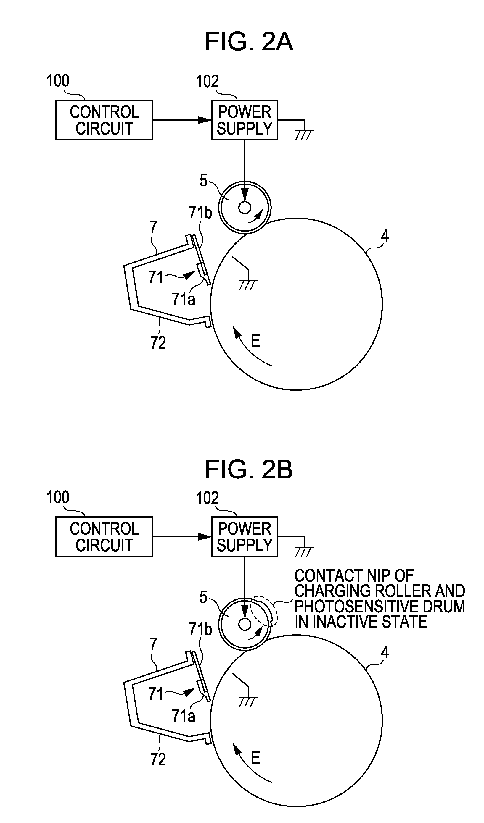
[0011]According to an aspect of the present invention, an image forming apparatus includes a rotatable image bearing member on which a toner image is capable of being formed, a charging roller rotatable in contact with the image bearing member, and a controller configured to control a voltage applied to the charging roller. The controller is capable of applying a control bias to between the charging roller and the image bearing member before rotation of the image bearing member and the charging roller starts, the control bias having the same polarity as that of a bias applied in image forming. According to another aspect of the present invention, an image forming apparatus includes a rotatable image bearing member on which a toner image is capable of being formed, a charging roller rotatable in contact with the image bearing member, and a controller configured to apply a voltage to the charging roller such that unevenness of toner contamination on the charging roller is reduced before applying an image forming bias.

Problems solved by technology

During such a process, in particular in low-temperature environment, the toner remaining after transferring may escape from capture by the cleaning member and that toner may contaminate the charging roller.
The contamination like this may hinder the charging roller from uniformly charging the surface of the photosensitive drum.
This may lead to unevenness in charging of the surface of the photosensitive drum and may result in a poor image quality.
Accordingly, both of them result in an increase in cost and size.
If contamination of the charging roller with toner locally occurs or a large amount of toner is attached, unevenness in charging causing an adverse effect on an image is present in the surface of the photosensitive drum.
In this case, the above-described approaches are considered to be unnecessary.
However, the results of a close study made by the inventors reveal that there is a case where, even if toner gradually contaminates the charging roller over its entire surface uniformly, an adverse effect on an image resulting from unevenness in charging caused by toner contamination of the charging roller is present.
The adverse effect on an image can be an unnecessary transverse line appearing in the image in a cycle of the charging roller.

Method used


Image

  • Image forming apparatus
  • Image forming apparatus
  • Image forming apparatus

Examples


first embodiment

[0058]before the driving of the drum 4 starts, a bias of approximately −500 V is applied as the bias VA to the charging roller 5 for approximately 500 msec.

[0059]The results of a study made to determine an advantage on the occurrence of unnecessary transverse lines in an image in the first comparative example and the first embodiment are shown in Table 1. FIG. 5 illustrates a sequence chart of the bias VA before the driving of the drum starts in the first comparative example and the first embodiment. Hereinafter, the time of application of the bias VA is defined as a period of time of applying the bias to the charging roller 5 within a period of time from when a print start signal Sis input into the control circuit 100 to when the drive motor M is activated in response to the print start signal S and the driving of the drum 4 starts.

[0060]A method for determining the level of the occurrence of unnecessary transverse lines in an image is described below. First, the driving of the dru...


PUM


Abstract

An image forming apparatus includes an image bearing member and a charging roller rotatable in contact therewith. Before driving of the image bearing member starts, a bias having the same polarity as that of an image forming bias is applied between the charging roller and the image bearing member. The time of application of the bias varies with the accumulated time of rotation of the image bearing member or the time of making the driving of the image bearing member inactive.

Description

BACKGROUND OF THE INVENTION[0001]1. Field of the Invention[0002]The present invention relates to an image forming apparatus that forms a latent image on an image bearing member by, for example, electrophotography or electrostatic recording, develops the latent image, and obtains a visible image.[0003]2. Description of the Related Art[0004]An image forming apparatus, such as an electrophotographic copier or an electrophotographic printer, often uses a charging member for uniformly charging the surface of an image bearing member. A commonly used example of the charging member is a charging roller rotated in contact with the image bearing member (hereinafter referred to as the photosensitive drum) so as to follow rotation of the image bearing member being driven. A typical image forming process performed in the photosensitive drum and its neighboring components in such an image forming apparatus can include the following processing: uniform charging of the surface of the photosensitive...

Claims


Application Information

Patent Timeline
IPC IPC(8): G03G15/02
CPCG03G15/0266G03G15/0225
Inventor MITSUI, YOSHIHIROAGATA, SHINICHI
Owner CANON KK
Learn More