Drag Reduction of a Tractor Trailer Using Guide Vanes
a technology of tractor trailer and guide rod, which is applied in the field of tractor trailers, can solve the problems of large inconvenience of extending and collapsing the device on the back of the tractor trailer, heavy weight of current boat-tail and planar cavity designs, and reduce the weight and simplicity of the device, and reduce the cost. , the effect of reducing the cos
- Summary
- Abstract
- Description
- Claims
- Application Information
AI Technical Summary
Benefits of technology
Problems solved by technology
Method used
Image
Examples
example 1
Computational Fluid Dynamic Analysis
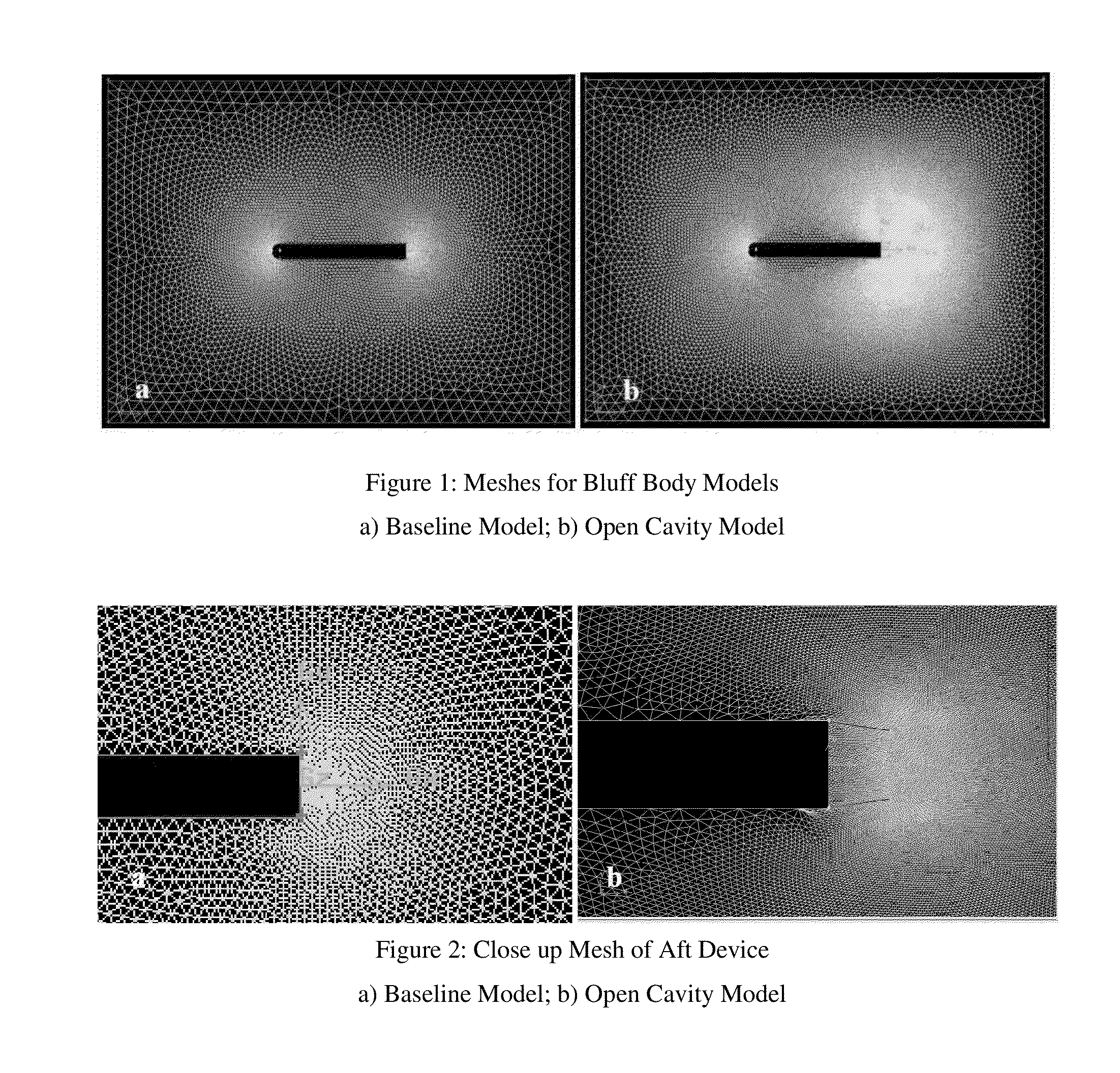
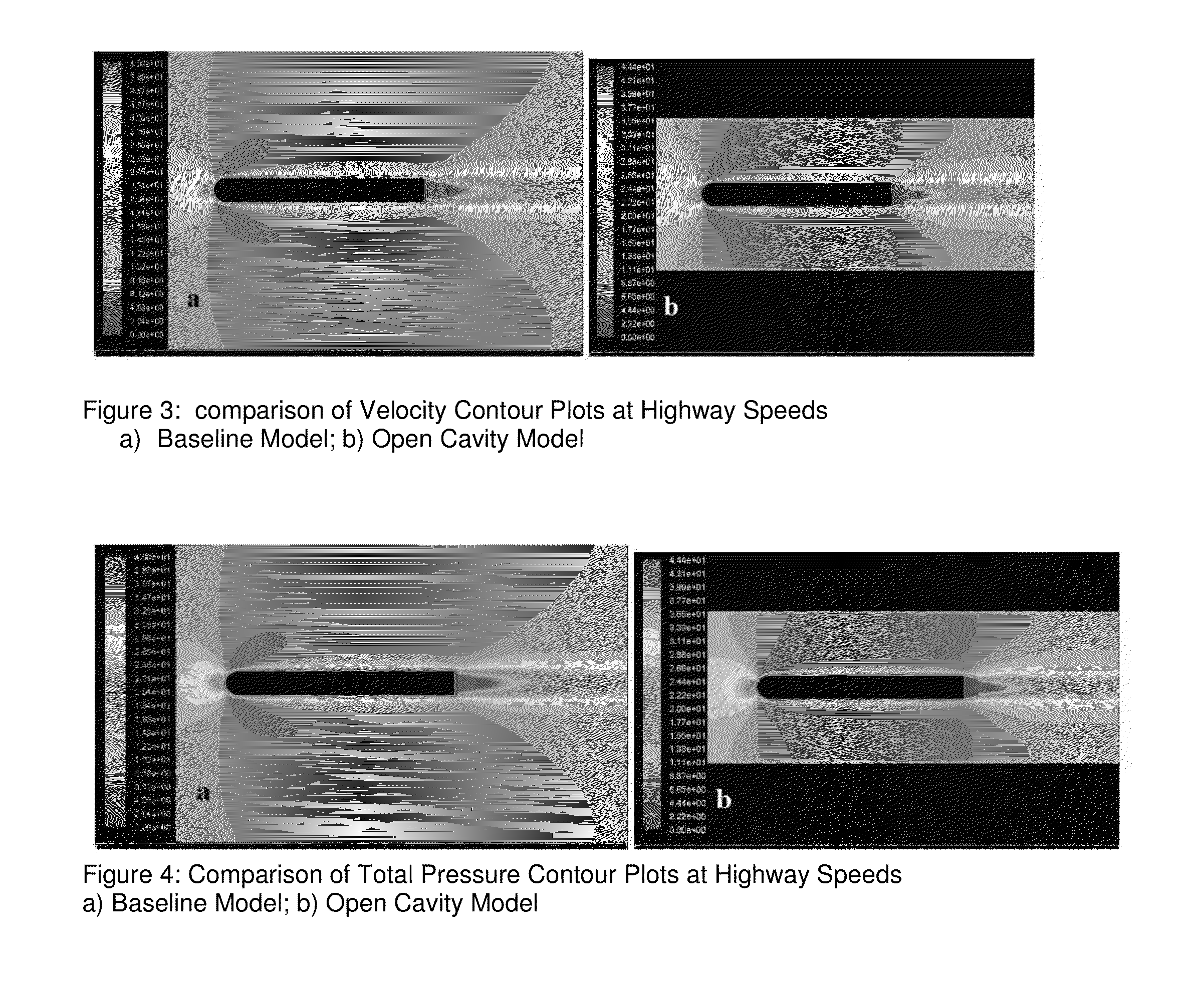
[0070]This Example sets forth a description of the computational fluid dynamic (CFD”) analysis used to investigate the potential of drag reduction with arc-shaped vanes. Using the data from the initial wind tunnel testing in Japan as a starting point, a comprehensive CFD optimization study was initiated. The purpose of this study was to use relationships between boundary layer formation, thickness and the geometry of the vanes to ultimately find out the optimal geometry of the vanes. In this way, through continually optimizing the computer model, a good correlation between model geometry and drag reduction could be obtained.
[0071]Before getting into detailed quantitative studies on arc vanes, the CFD study began with very general qualitative studies. The first of these studies was the two dimensional modeling of a simple bluff body, the length and width of a tractor trailer both with and without a drag reducing device. The bluff body was modeled f...
example 2
Experimental Apparatus
[0079]This Example describes the experimental apparatus used in the following Examples. All wind tunnel testing was conducted in the Clarkson University high speed Eiffel type wind tunnel on a 1:15.25 scale tractor trailer model. The biaxial force balance set-up was taken directly from J. D. Coon's thesis work (see “SAE Wind Tunnel Test Procedure for Trucks and Buses.” SAE International. 1981), as very little is changed from his original set-up.
[0080]During testing, the maximum velocity achieved by the wind tunnel was approximately 37 m / s, or 82.8 mph. Based on trailer width, the Reynolds number produced by this velocity is about 3.9×10⁵. If it is assumed that a full scale tractor trailer experiences an average wind speed of 70 mph, or 31.3 m / s, and that the usual width of a tractor trailer is 2.46 meters, the resulting full scale Reynolds number is approximately 5×10⁶. The SAE Wind Tunnel Test Procedure for Trucks and Buses' suggests a minimum experimental Rey...
example 3
Wind Tunnel Models
Initial Testing
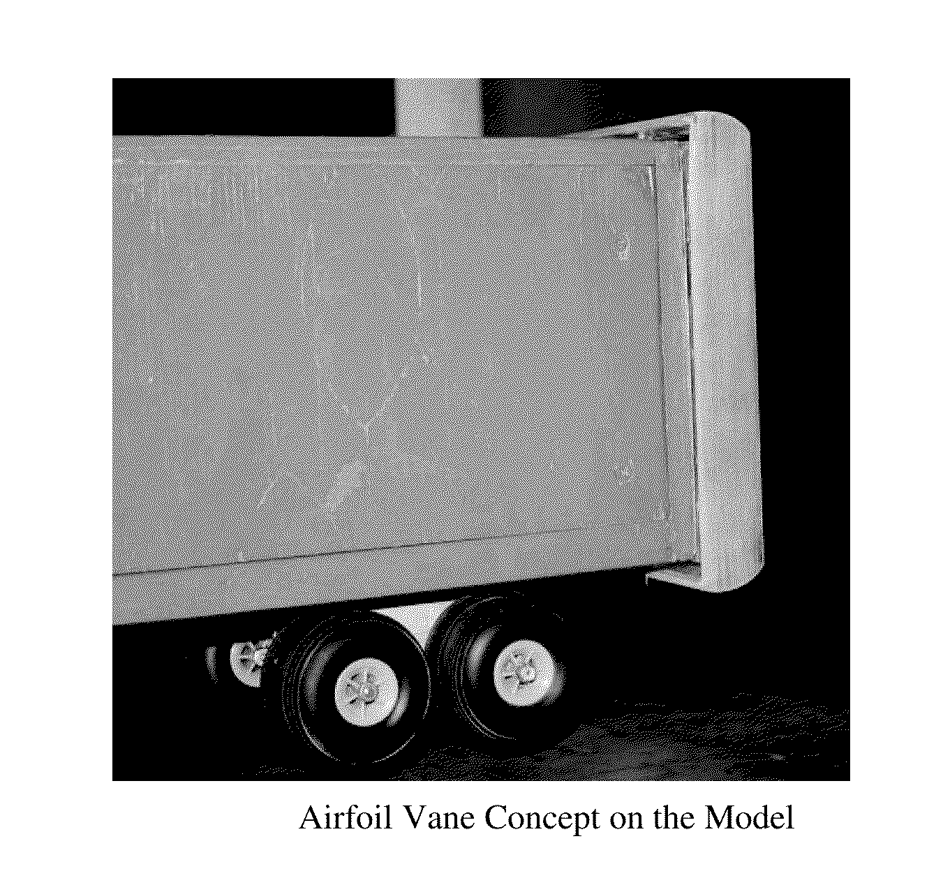
[0113]This Example describes certain “initial testing” of the “wind tunnel models.” The purpose of the initial testing was to simply get an idea for how Kato's un-optimized scaled geometry worked on the tractor trailer model. Because it was a preliminary testing step, only two studies were carried out: a yaw angle study on Kato's design, and a study that examined the change in drag reduction that different configurations cause. A description of testing that occurred during this phase is set forth herein.
[0114]Using the Kato et al investigation as a starting point, the initial, exploratory design was modeled using optimal dimensions from the paper. A schematic illustrated in FIG. 15 shows Kato's experimental set-up (see also Frey, K. (1933), “Verminderung des Stroemungswiderstandes von Koepern durch Leitflaechen,”Forschung Ing. Wesen, March / April, pp. 67-74). The optimum configuration of vanes is given as ratios of the vane arc-radius to body width, v...
PUM
 Abstract
Description
Claims
Application Information
 - R&D
- Intellectual Property
- Life Sciences
- Materials
- Tech Scout
- Unparalleled Data Quality
- Higher Quality Content
- 60% Fewer Hallucinations
Browse by: Latest US Patents, China's latest patents, Technical Efficacy Thesaurus, Application Domain, Technology Topic, Popular Technical Reports.
© 2025 PatSnap. All rights reserved.Legal|Privacy policy|Modern Slavery Act Transparency Statement|Sitemap|About US| Contact US: help@patsnap.com


